Villiers Magneto Rebuild
Villiers Magneto Rebuild
These simplified instructions are intended as a guide for anyone attempting to strip down and repair a similar ignition system. The Atco mower which was being serviced was the Deluxe model from the 1930s although the same engine was used on many of the company's earlier models from the 1920s as well as later machines up to 1939 and after.
It is advisable to have a set of Whitworth combination spanners available. These are a huge benefit compared with using a “close match” metric or standard Imperial spanner. The use of adjustable spanners is particularly unsuitable when having to apply the rather large torques for removing or re-fitting the flywheel.
1: Ignition System Access
1: Ignition System Access
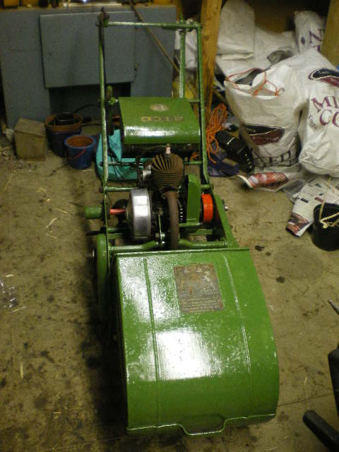
Gain access to the ignition system by prising off the aluminium casing from the side of the engine. This will reveal a heavy brass flywheel with access holes for checking points.
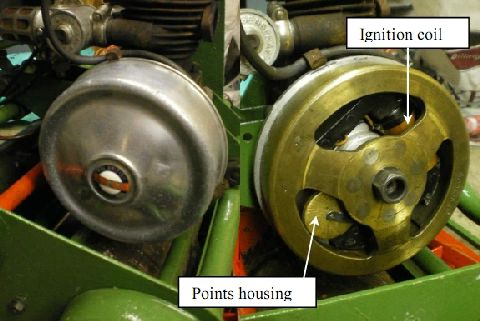
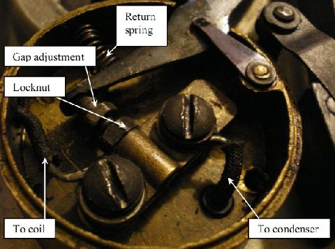
The contact breaker points are housed beneath the brass cap (see image) whose retaining arm must be swung sideways to open the cap. With a little careful manoeuvring, the cap can be removed through the access holes in the flywheel and the points gap can be checked and adjusted. The gap should be checked (probably 0.015”) and adjusted using the threaded adjuster and locknut as required.
2: Removing The Flywheel
2: Removing The Flywheel
To perform any maintenance on the ignition system other than cleaning or adjusting the points, it is necessary to remove the flywheel. This is best achieved by jamming the flywheel (to prevent its rotation) with a wooden wedge between its outer circumference and a mower cross bar.
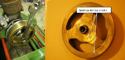
Then, using an appropriate ring spanner, give a sharp strike to the ring spanner with a hammer in an anticlockwise direction to shock the nut undone (see image). A 1/2in Whitworth ring spanner can be used however, if one can be found, Villiers also produced a special spanner (called a Hammertite spanner) for this specific task. This has a ring spanner at one and a place to hit with a hammer at the other.
If successful, the nut will undo by about one or two full turns before apparently locking-up again. You need to shock this anticlockwise again which will then prise the conical flywheel mount from the mating taper on the crankshaft; the nut is captive but rotates within the flywheel.
The magneto flywheel contains a pair of permanent magnets and the original Villiers maintenance advice was to place a piece of iron (e.g. a spanner) to bridge across the poles thus preventing loss of magnetic flux.
3: Removing The Armature Back Plate
3: Removing The Armature Back Plate
To inspect or service the ignition system, it is easiest to remove the whole magneto assembly from the engine. Disconnect the H-T lead from the spark plug. Loosen the set screw which is behind the armature back plate and which clamps the back plate on to the engine’s crank housing.
The back plate is also clamped to the crank housing with a support bracket. On some Villiers ignition system, there is an alternative clamping arrangement allowing some rotation of the back plate so as to “tune” the ignition timing.
With a bit of back-and-forth rotation of the back plate around the axis of the crankshaft, the entire armature back plate should come away from the engine (see image) and can be overhauled more easily on a well-lit and clean workbench (to avoid losing small but crucial parts).
4: Checking or Replacing The Ignition Coil
4: Checking or Replacing The Ignition Coil
If the engine is suffering from a weak (or no) spark, then the problem may be within the magneto coil. This can be checked using a voltmeter (to measure resistance) but it is required to remove the wire connection between the coil and the points.
The primary winding should have a resistance of just a few Ohms (measured between ground - either end of the iron core - and the socket in to which the points wire was screwed.) The secondary winding resistance should be 3-5k Ohms and this can be measured between the side terminal connection to the H-T lead and ground.
The most likely scenario with an old magneto coil is that it has some internal corrosion and the secondary winding (which is wound from extremely fine copper wire) has broken.
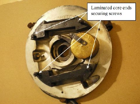
The coil can be removed from the “shoe” shaped laminated metal core ends by removing the nuts on the rear side of the back plate. You may need to use a screwdriver to counteract the torque on the corresponding screws which hold these core ends on to the back plate (see image). The core ends will then lift from the back plate and the coil can be pulled free from these shoes.
Replacement coils can be sourced via the internet but ensure that you specify the correct length and end diameters as there are various models available. Replacements are not cheap (perhaps £50) and beware of untested items for sale on auction sites!
With the flywheel removed, you now have excellent access to the contact breaker points and can provide a proper inspection.
5: Contact Breaker Points Maintenance
5: Contact Breaker Points Maintenance
Disassemble the points by removing the contact breaker arm. This is held in position by a clip and spring. Note that the spring may easily be dropped on the floor – hence the need for a clean, well-lit work surface.
Loosen and remove the two screws which hold down the brass strip and which also clamp the low tension wire and the connection to the condenser. This brass strip is isolated from ground by insulating posts which should be inspected for cracks or other degradation. Note the order of construction of these components so that it can be rebuilt easily.
With the upper components removed, the base of the points housing can be unscrewed from the back plate and the capacitance of the condenser can be measured. The condenser rarely fails.
Reassembly is generally the reverse of the disassembly instructions above, but pay particular attention to the cleanliness of the contact breaker points. Even a thin film of oil from dirty feeler gauges can foul the points surfaces sufficiently to prevent a good spark.
6: Inspecting The H-T cable
6: Inspecting The H-T cable
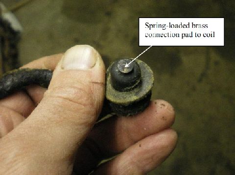
Inspect the H-T cable for continuity between the spring-loaded coil end and the spark plug connection end.
Check also for cracks in the cable insulation. Replacement cables can be sought from the internet, but repairs can also be made to cracked or otherwise damaged H-T leads using appropriately-sized adhesive heatshrink.
7: Re-fitting The Flywheel & Final Set-up
7: Re-fitting The Flywheel & Final Set-up
Hold the contact breaker arm open while refitting the flywheel on to its tapered shaft. There are timing marks on the flywheel which should be aligned with the notch on the crankshaft end. This will ensure correct spark timing.
The flywheel nut will need to be tightened sufficiently to prevent any movement on the tapered shaft. If it is slightly loose, the flywheel may slip following a misfire, the timing will be compromised and the engine will run either roughly or not at all. Therefore, tighten the flywheel using the ring spanner and hammer arrangement previous described for removal, but this time for tightening (clockwise).
Finally, re-set the contact breaker points gap.
Check for a spark by unscrewing the spark plug, attaching the H-T lead and resting the threads of the plug against the surface of the cylinder’s cooling fins.