Freeing A Seized Atco Cone Clutch
Freeing A Seized Atco Cone Clutch
This simple cone clutch was used on a variety of Atco products including the “Lightweight” lawnmower and also, as in this case, the Atco Scythe. During restoration work on items which have been left outside or inactive for many years, parts which should me moving – aren’t!
The following instructions are taken from a simple overhaul of a seized clutch without the aid of any specialist tools. We hope they will be of some help to others. These instructions have been written without access to the original manual for this equipment.
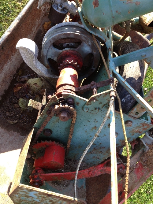
Figure 1: The clutch and chain drive to the reciprocating blade of this Atco Scythe. Exposure to the elements had taken its toll on most aspects of this machine.
1: Removing Clutch Assembly
1: Removing Clutch Assembly
The first step is to remove the clutch assembly from the drive train. This is required anyway to gain access to the flywheel retaining nut and thereby access to the ignition system. The chain shown in Figure 1 has a removable link making its disassembly simple. The use of penetrating oil then allows the sprocket retaining nut to be removed, followed by the sprocket itself from the splined shaft.
More penetrating oil enables the three nuts and bolts which hold the clutch ball bearing cassette to be removed, and after releasing any tension on the clutch cable, disassemble the clutch release forks assembly. A useful tip at this point is to store the disassembled nuts, washers and spring in the order ready for reassembly….or to photograph the details of this assembly order.
Depending on how much clearance you have, you may or may not be able to remove the clutch assembly from the machine. In the case of this Atco Scythe, the engine needed to be shifted slightly to provide sufficient clearance to remove the clutch. The clutch is attached to the flywheel via the tabbed shaft and the associated slots in the outer clutch body housing as shown in Figure 2.
2: View of Flywheel Assembly
2: View of Flywheel Assembly
It is tempting to try to remove the slotted screw head which is presented within the clutch housing at this time, however, it’s not necessary to remove this for a general clutch overhaul and, at time of writing, the author still doesn’t know if this is a left- or right-handed thread; the direction of rotation would suggest a left-hand thread to be most appropriate. But in summary, the screw’s removal is not fundamental to separation of the friction surfaces.
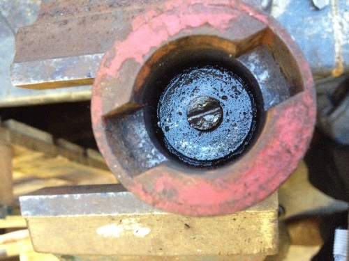
Figure 2: View of flywheel end of clutch assembly.
3: Clutch Assembly Removed From Engine
3: Clutch Assembly Removed From Engine
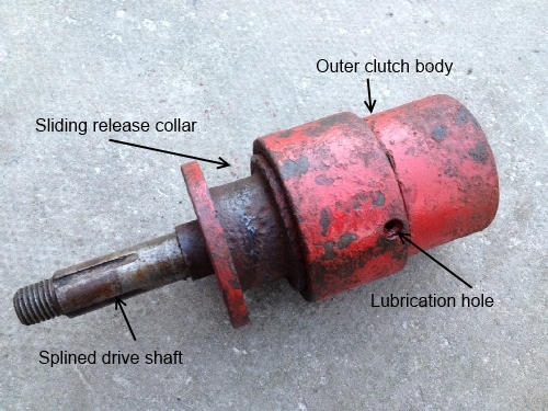
Figure 3: Clutch assembly once removed from engine. At this point, the friction surfaces are seized and stuck together.
In this case, it was possible to begin rotating the outer clutch body relative to the drive shaft, but with an insufficient clearance to allow the clutch to mesh and disengage to any useful degree.
The main seizure problem was that the sliding release collar simply wasn’t (sliding) and was stuck fast to the drive shaft. The lubrication hole is of some use here because it allows penetrating oil to lubricate the engine end of the drive shaft. Note that the lubrication hole doesn’t duct lubricant on to the friction surfaces, but more lubricates components within the outer clutch body. Penetrating oil should also be introduced from the sprocket end in an attempt to free the release collar.
4: Removing Collar From Drive Shaft
4: Removing Collar From Drive Shaft
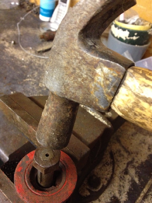
Figure 4: Holding the release collar whilst tapping the drive shaft free.
The next operation is somewhat controversial: you need to begin working the drive shaft back and forth, applying more penetrating oil as necessary, so that little-by-little, the drive shaft begins to move relative to the release collar. I first tried a 3-legged wheel puller for this operation but found that I had applied so much force without any success that I feared breaking off pieces of the release collar. Figure 4 shows the sprocket retaining nut having been screwed on to the end of the drive shaft to be flush with the threaded end of the shaft. This can then be tapped “sharply” with a hammer to help shock the shaft free of the collar whilst supporting the release collar on the jaws of a vice. It has to be understood here, that there is a significant risk of deforming the threads of the shaft, so some judgment needs to be made as to how hard to strike the shaft & nut. Tapping the shaft and clutch housing in opposing directions with the aid of penetrating oil in this case gradually freed the release collar from the shaft and allowed disassembly of the mating clutch cone surfaces as shown in Figure 5.
5: Release Collar and Cone Separated
5: Release Collar and Cone Separated
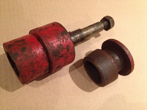
Figure 5: Release collar and its cone shown separated from main clutch parts.
The main clutch components are now separated and can be cleaned and reassembled, noting that the retaining screw shown in Figure 2 needn’t be disturbed.
Cleaning of the keyed drive shaft as shown in Figure 6 (being careful not to lose the Woodruff key) can now take place. Cleaning of the hole through the release collar clutch portion and its keyway should allow the release collar to slide easily along the drive shaft. Penetrating oil on a rag is sufficient to clean such surfaces. I didn’t bother cleaning anything but loose rust from the mating cone surfaces and assumed that the engagement of the cone surfaces during normal drive operation would adequately bed-in the parts.
6: Splined Shaft
6: Splined Shaft
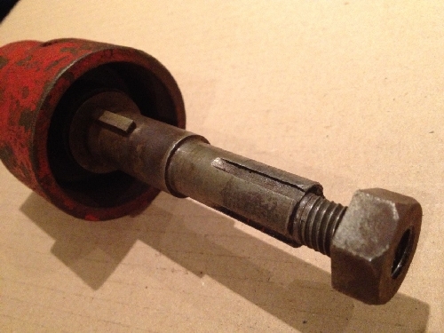
Figure 6: Splined drive shaft showing the Woodruff key which transmits the driving torque from the driven clutch half to the drive shaft.
7: Reassembly
7: Reassembly
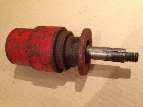
Figure 7: Reassembled clutch components.
Reassembling all the components in the same order as they were removed completes the task. I gave the clutch spring a slight stretch before re-fitting it as I assumed that the passage of time and the elements would have weakened this somewhat. I also washed through the ball race with petrol and re-greased it prior to reassembly in the end frame of the Atco Scythe.
Finally, you need to adjust the clutch release forks’ position and cable tension so that the clutch properly disengages (one doesn’t want the blade of an Atco Scythe to twitch when it should be stationary) and that the forks aren’t in contact with the release collar when the clutch is engaged.
The video shows the Atco Scythe up-and-running after restoration.