B&S Governor linkage question
Hi, can somebody please help me with the governor linkage on a B&S 141302 (6HP, I think). There is a plastic vane near the flywheel from which I have cobbled together a linkage which now holds the throttle shut when the engine is running but the only way I have to increase the revs, is to turn in the idle screw on the throttle. There is no governor arm on the crankcase to link it to, so I am a bit stumped.
I have not been able to find any photos or descriptions online of this particular setup. Can anyone help with this please?
Thanks,
Oscar
Forums

Thanks Wristpin, that is most
Thanks Wristpin, that is most useful. The engine doesn't have a rod and arm that comes out of the crankcase for the governor, it just has the plastic vane near the flywheel. However, I do have one of those U shaped arms shown in Fig 74 of your attachment, so that seems to be the way forward.
Many thanks
Ah, should have paid more
Ah, should have paid more attention ! Air vane Governor . So it’s the vane that’s trying to close the throttle under the influence of the air pressure from the flywheel. I’ll see if I’ve got anything a bit older.
EDIT
The plot thickens.
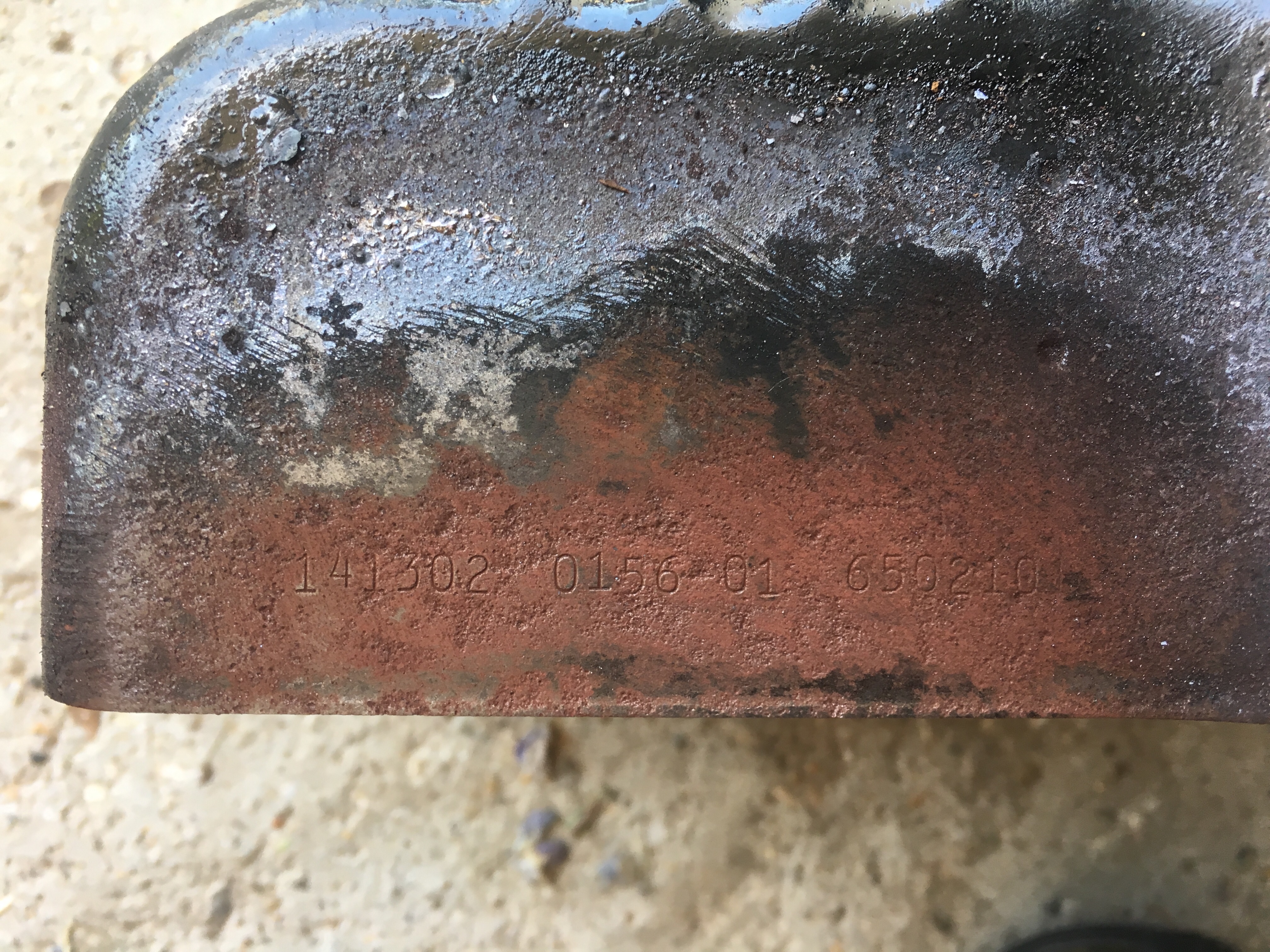
I have the hard copy parts lists and micro fiche for Models 141300- 141457, types 110 - 0183 ., which, unless the unaccustomed warmth has got to my brain, should cover the model and type on your engine’s blower housing. However, nowhere do they show an air vane governor, only a mechanical one. So unless I’m having a senior moment it has to be considered that someone has swapped housings at some point and your engine is not what it says it is.
Interesting! The engine is
Interesting! The engine is currently fitted to a Mayfield Scythe which I am trying to get up and running. Are there any other places to look for identifying numbers, maybe on the block itself? I have taken pictures from different angles. Would that help?
Unfortunately Briggs only put
Unfortunately Briggs only put ID numbers on the blower housing. However a starting point is whether the cylinder block material is aluminium alloy or cast iron. Also some fairly wide angle images of the air vane and carburettor areas will be more help than detailed close-ups.
Possibly an Allen Mayfield collector will be able to tell you what engine should be on a given model - chassis numbers and images again.
Thanks again Wristpin,
Thanks again Wristpin,
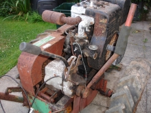
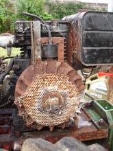
I have been doing some hunting around myself and I found, on an old laptop, some photos taken when I bought the thing in 2011 (including the partial linkage). I had forgotten what a mess it was in!
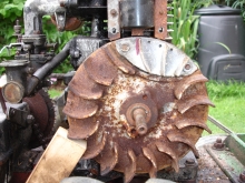
The photos will prove useful in getting the linkage right but I would still like to find out what the engine model is if possible (the shroud looks to be the same one). To that end, I have included a few 'general' pics. To be honest, I have no idea if the cylinder block material is aluminium alloy or cast iron. How do I tell please?
Thanks in advance.

Aluminium is non magnetic,
Aluminium is non magnetic, iron is.
I think that the fog is
YI think that the fog is clearing, just a bit..
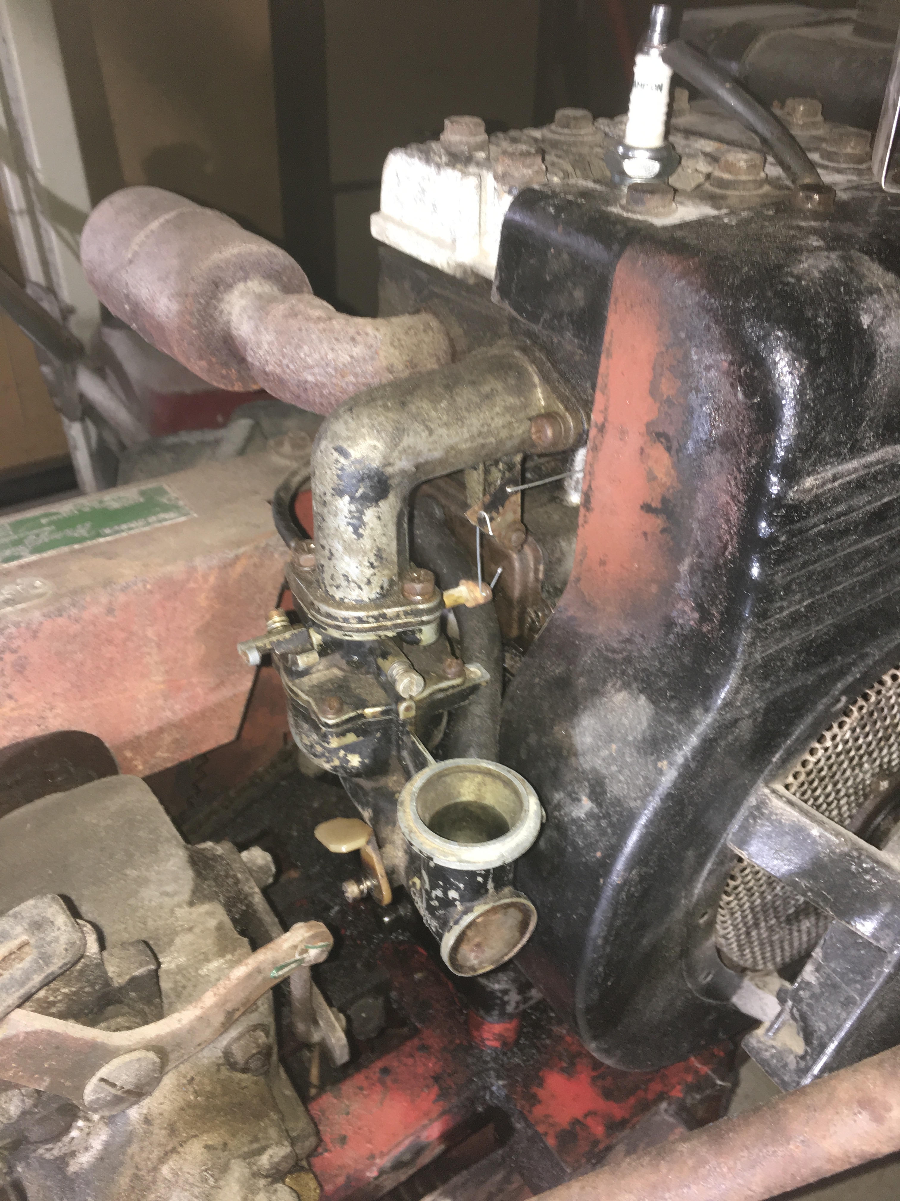
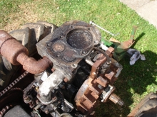
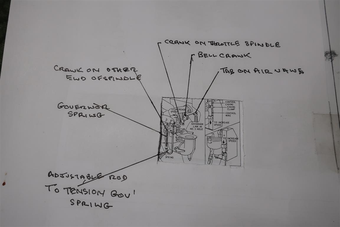
In your third image, just visible to the left of the coil is the tab on the air vane. A short rod should connect that tab to a bell crank (not there but shown on my diagram)
The other arm of the bell crank has a rod connecting to a short crank on the end of the throttle spindle.
On the opposite end of the throttle spindle there is a similar short crank with the governor spring hooked into it .
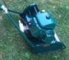
The other end of the spring hooks into the J shaped rod that slides up and down to tension it . in the case of a fixed speed engine that rod is held in the desired position by an thumb wheel. In your 4th image that thumb wheel is visible to the left of the L shaped inlet manifold.
In a variable speed application that rod or something similar is free to move under the control of the throttle cable.
Good call on the block -
Good call on the block - forgot about a magnet! It's Aluminium.
I think I am on my way now. Thanks for the help and I will report back if I ever get it running satisfactorily.
Oscar
Hi, just a quick update and a
Hi, just a quick update and a thanks for all your help. Scythe is running really well now with a mixture of home made and standard parts for the governor mechanism.
Video here if anyone is interested - https://www.youtube.com/watch?v=LrQG3D-_aIw
Thanks again,
Niscars
Not totally clear from your
Not totally clear from your image but understanding what the governor does and how it achieves it may help.
With the engine running the rod and arm that comes out of the crankcase is moved in a direction to close the throttle.
The handle bar throttle lever via a cable and a spring (the governor spring) is connected to the above arm an tries to hold the throttle open . When the closing force of the arm and the pull of the spring are equal that is the governed speed.
I am going to attach some scans from the Briggs workshop Repair Instructions which may assist you. You just need to try and match your set up to one of the options!
https://www.dropbox.com/s/s5tnrj3eemmiswz/Briggs%2014000%20governor%20o…