Shanks Lawnmower Patent No 1147 Described in Practical Mechanics Journal
The Shanks 1855 pull-along chariot-style mowing and rolling machine (Patent No 1147) was covered several times in the press during 1855 and 1856.
This extract from the Practical Mechanic's Journal includes a detailed diagram of the mower with an explanation of its operation.
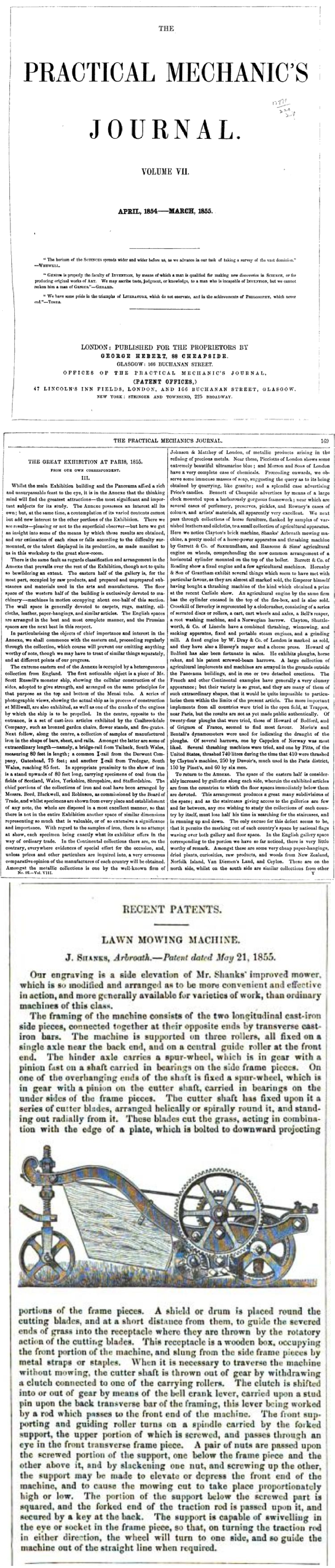
RECENT PATENTS. LAWN MOWING MACHINE.
J. SHANKS, Arbroath.-Patent dated May 21, 1855.
Our engraving is a side elevation of Mr. Shanks' improved mower. which is so modified and arranged as to be more convenient and effective in action, and more generally available for varieties of work, than ordinary machines of this class.
The framing of the machine consists of the two longitudinal cast-iron side pieces, connected together at their opposite ends by transverse cast- iron bars. The machine is supported on three rollers, all fixed on a single axle near the back end, and on a central guide roller at the front end. The hinder axle carries a spur-wheel, which is in gear with a pinion fast on a shaft carried in bearings on the side frame pieces. On one of the overhanging ends of the shaft is fixed a spur-wheel, which is in gear with a pinion on the cutter shaft, carried in bearings on the under sides of the frame pieces. The cutter shaft has fixed upon it a series of cutter blades, arranged helically or spirally round it, and standing out radially from it. These blades cut the grass, acting in combination with the edge of a plate, which is bolted to downward projecting
portions of the frame pieces. A shield or drum is placed round the cutting blades, and at a short distance from them, to guide the severed ends of grass into the receptacle where they are thrown by the rotatory action of the cutting blades. This receptacle is a wooden box, occupying the front portion of the machine, and slung from the side frame pieces by metal straps or staples. When it is necessary to traverse the machine without mowing, the cutter shaft is thrown out of gear by withdrawing a clutch connected to one of the carrying rollers. The clutch is shifted into or out of gear by means of the bell crank lever, carried upon a stud pin upon the back transverse bar of the framing, this lever being worked by a rod which passes to the front end of the machine. The front sup- porting and guiding roller turns on a spindle carried by the forked support, the upper portion of which is screwed, and passes through an eye in the front transverse frame piece. A pair of nuts are passed upon the screwed portion of the support, one below the frame piece and the other above it, and by slackening one nut, and screwing up the other, the support may be made to elevate or depress the front end of the machine, and to cause the mowing cut to take place proportionately high or low. The portion of the support below the screwed part is squared, and the forked end of the traction rod is passed upon it, and secured by a key at the back. The support is capable of swivelling in the eye or socket in the frame piece, so that, on turning the traction rod in either direction, the wheel will turn to one side, and so guide the machine out of the straight line when required.
PublicationOtherDateSourceGoogle Books/The Practical Mechanic's Journal/Vols7-8/1855/P248Link