1855-05-21 Shanks Improvements In Mowing Machines Patent No 1147
A.D. 1855
N° 1147.
Mowing Machines.
LETTERS PATENT to James Shanks, of Arbroath, in the County of Forfar, North Britain, Machinist, for the Invention of "IMPROVEMENTS IN MOWING MACHINES."
Sealed the 16th November 1855, and dated the 21st May 1855.
PROVISIONAL SPECIFICATION left by the said James Shanks at the Office of the Commissioners of Patents, with his Petition, on the 21st May 1855.
I, JAMES SHANKS, of Arbroath, in the County of Forfar, North Britain, Machinist, do hereby declare the nature of the said Invention for "IMPROVE- MENTS IN MOWING MACHINES" to be as follows, that is to say :-
This Invention relates more especially to that class of machines used for mowing or cutting short grass and vegetables or plants, commonly known as "lawn mowing machines," and it consists in the so modifying and arranging such cutters as to render them more convenient and effective in action and more generally available for varieties of work than has hitherto been the case.
This improvement is effected by adapting a carrying or supporting ground wheel to the machine in such manner as to make it easily workable, either for the purposes of a large mower, where extended areas of grass are to be cut, or for the cutting of verges and borders or detached spaces. The improved machine is drawn by a handle attached to the vertical spindle of the front guide wheel instead of being pushed before the operator, as heretofore. The guide wheel spindle is adjustable as to height by a nut upon it above and below the socket in which it swivels for the turning movement, the lower part of the spindle being forked and fitted with a stud pin or axle in the usual manner for the attachment of the guide wheel. The disposition of this wheel in the centre of the machine leaves the sides quite clear for moving verges or borders, so that in changing from one class of work to another no change is necessary in any of the parts unless the height at which the cut is to be made should require alteration, when it can be done at once by shifting the adjusting nuts on the front guide wheel spindle.
SPECIFICATION in pursuance of the conditions of the Letters Patent, filed by the said James Shanks in the Great Seal Patent Office on the 21st November 1855.
TO ALL TO WHOM THESE PRESENTS SHALL COME, I, JAMES SHANKS, of Arbroath, in the County of Forfar, North Britain, Machinist, send greeting.
WHEREAS Her most Excellent Majesty Queen Victoria, by Her Letters Patent, bearing date the Twenty-first day of May, in the year of our Lord One thousand eight hundred and fifty-five, in the eighteenth year of Her reign, did, for Herself, Her heirs and successors, give and grant unto me, the said James Shanks, Her special license that I, the said James Shanks, my executors, administrators, and assigns, or such others as I, the said James Shanks, my executors, administrators, or assigns, should at any time agree with, and no others, from time to time and at all times thereafter during the term therein expressed, should and lawfully might make, use, exercise, and vend, within the United Kingdom of Great Britain and Ireland, the Channel Islands, and Isle of Man, an Invention for "IMPROVEMENTS IN MOWING MACHINES," upon the condition (amongst others) that I, the said James Shanks, by an instrument in writing under my hand and seal, should particularly describe and ascertain the nature of the said Invention, and in what manner the same was to be performed, and cause the same to be filed in the Great Seal Patent Office within six calendar months next and immediately after the date of the said Letters Patent.
NOW KNOW YE, that I, the said James Shanks, do hereby declare the nature of my said Invention, and in what manner the same is to be performed, to be particularly described and ascertained in and by the following statement in writing, reference being had to the accompanying Drawings, and to the letters and figures marked thereon, that is to say :-
My said Invention relates more especially to that class of machines used for mowing or cutting short grass and vegetables or plants, commonly known as "lawn mowing machines ;" and it consists in the so modifying and arranging such cutters as to render them more convenient and effective in action and more generally available for varieties of work than has hitherto been the case.
This improvement is effected by adapting a carrying or supporting ground wheel to the machine in such manner as to make it easily workable either for the purposes of a large mower, where extended areas of grass are to be cut, or for the cutting of verges and borders or detached spaces. The improved machine is drawn by a handle attached to the vertical spindle of the front guide wheel instead of being pushed before the operator, as heretofore. The guide wheel spindle is adjustable as to height by a nut upon it above and below the socket in which it swivels for the turning movement, the lower part of the spindle being forked and fitted with a stud, pin, or axle in the usual manner for the attachment of the guide wheel. The disposition of this wheel in the centre of the machine leaves the sides quite clear for mowing verges or borders, so that in changing from one class of work to another, no change is necessary in any of the parts unless the height at which the cut is to be made should require alteration, when it can be done at once by shifting the adjusting nuts on the front guide wheel spindle.
And in order that my said Invention may be properly understood, I shall now proceed to describe the explanatory Figures on the Sheet of Drawings hereunto attached.
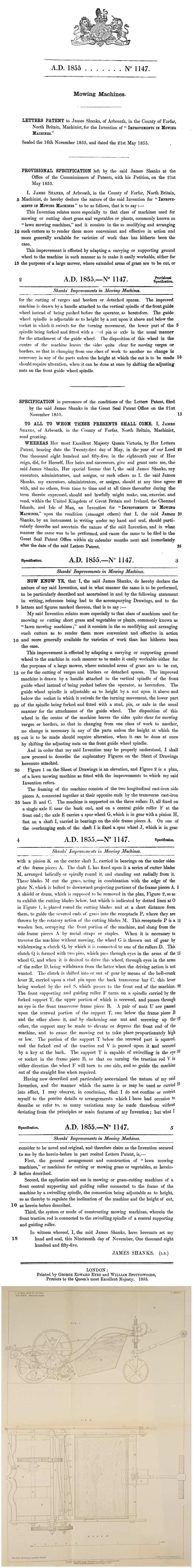
Figure 1 on the Sheet of Drawings is an elevation, and Figure 2 is a plan, of a lawn mowing machine as fitted with the improvements to which my said Invention refers.
The framing of the machine consists of the two longitudinal cast-iron side pieces A, connected together at their opposite ends by the transverse cast-iron bars B and C. The machine is supported on the three rollers D, all fixed on a single axle E near the back end, and on a central guide roller F at the front end; the axle E carries a spur wheel G, which is in gear with a pinion H, fast on a shaft I, carried in bearings on the side frame pieces A. On one of the overhanging ends of the shaft I is fixed a spur wheel J, which is in gear with a pinion K on the cutter shaft L, carried in bearings on the under sides of the frame pieces A. The shaft L has fixed upon it a series of cutter blades M, arranged helically or spirally round it, and standing out radially from it. These blades M cut the grass, acting in combination with the edge of the plate N, which is bolted to downward projecting portions of the frame pieces A. A shield or drum, which is supposed to be removed in the plan, Figure 2, so as to exhibit the cutting blades below, but which is indicated by dotted lines at O in Figure 1, is placed round the cutting blades and at a short distance from them, to guide the severed ends of grass into the receptacle P, where they are thrown by the rotatory action of the cutting blades M. This receptacle P is a wooden box, occupying the front portion of the machine, and slung from the side frame pieces A by metal straps or staples. When it is necessary to traverse the machine without mowing, the wheel G is thrown out of gear by withdrawing a clutch Q, by which it is connected to one of the rollers D. This clutch Q is formed with two pins, which pass through eyes in the arms of the wheel G, and when it is desired to drive this wheel, through eyes in the arms of the roller D, being withdrawn from the latter when the driving action is not wanted. The clutch is shifted into or out of gear by means of the bell-crank lever R, carried upon a stud pin upon the back transverse bar C, this lever being worked by the rod S, which passes to the front end of the machine. The front supporting and guiding roller F turns on a spindle carried by the forked support T, the upper portion of which is screwed, and passes through an eye in the front transverse frame piece B. A pair of nuts U are passed upon the screwed portion of the support T, one below the frame piece B and the other above it, and by slackening one nut and screwing up the other, the support may be made to elevate or depress the front end of the machine, and to cause the mowing cut to take place proportionately high or low. The portion of the support T below the screwed part is squared, and the forked end of the traction rod V is passed upon it and secured by a key at the back. The support T is capable of swivelling in the eye or socket in the frame piece B, so that on turning the traction rod V in either direction the wheel F will turn to one side, and so guide the machine out of the straight line when required. Having now described and particularly ascertained the nature of Invention, and the manner which the same is or may be used or carried into effect, I may observe, in conclusion, that I do not confine or restrict myself to the precise details or arrangements which I have had occasion to describe or refer to, as many variations may be made therefrom without deviating from the principles or main features of my Invention; but what I consider to be novel and original, and therefore claim as the Invention secured to me by the herein-before in part recited Letters Patent, is,-
First, the general arrangement and construction of "lawn mowing machines," or machines for cutting or mowing grass or vegetables, as herein-before described.
Second, the application and use in mowing or grass-cutting machines of a front central supporting and guiding roller connected to the frame of the machine by a swivelling spindle, the connection being adjustable as to height, so as thereby to regulate the inclination of the machine and the height of cut, as herein-before described.
Third, the system or mode of constructing mowing machines, wherein the front traction rod is connected to the swivelling spindle of a central supporting and guiding roller.
In witness whereof, I, the said James Shanks, have hereunto set my hand and seal, this Nineteenth day of November, One thousand eight hundred and fifty-five.
JAMES SHANKS. (L.S.)
LONDON:
Printed by GEORGE EDWARD EYRE and WILLIAM SPOTTISWOODE, Printers to the Queen's most Excellent Majesty. 1855.