Pawl Puzzle
I have recently been restoring an American sidewheel known as Magic. I didn't take that much notice of the pawl arrangement when disassembling (rookie mistake of course) but have discovered the following unusual configuration now that I am putting it back together...
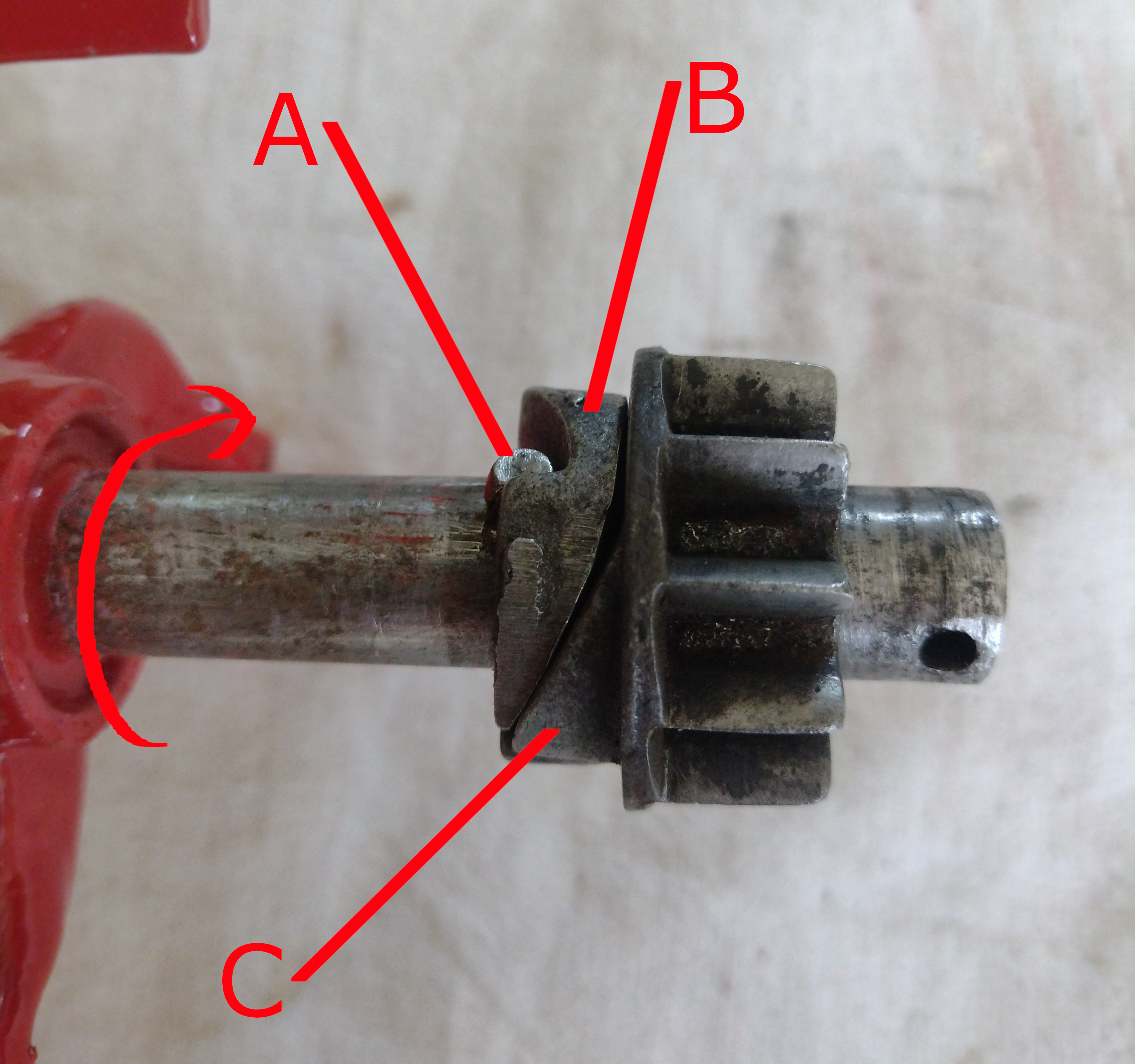
Component C is driven by the teeth on the inside of the wheel and engages with component B. This in turn rotates the cylinder in the direction indicated by the red arrow by engaging with lug A on the shaft.
So far so good, but look closely at components B and C. They are shaped to fit together well, which you might expect, except that when turning in the correct direction to drive the cylinder they would be forced apart by their respective shapes to disengage. On the other hand, in the configuration shown, pulling the mower backwards positively disengages the drive to the cylinder very easily because part C engages neatly with part B and the shape of part B pulls it away from the lug A.
This to me seems slightly counterintuitive as I would expect the components to be designed for optimum forward drive and mowing rather than for more effective disengagement when the mower is pulled backwards. I have tried various ways of assembling and cannot see any alternative way of putting the components on the shaft that will work. The equivalent components for the other end of the shaft are "handed" and fitting them on different ends makes no difference.
You will notice the hole on the end of the shaft. This had a split pin in it to stop part C from moving too far to the right (as seen in the picture).
With the split pin in place the configuration just about drives the cylinder so I am pretty sure that it's the correct assembly. I am wondering if some other components were missing when I bought the mower as it is after all over 100 years old. This could be simply a washer between part C and the split pin which would allow the drive to disengage but keep the assembly close enough to drive the cylinder. A better idea perhaps would be a coil spring which would push everything together for mowing but still allow the disengagement required.
I have seen plenty of sidewheel mowers over the years but nothing with a similar set up. My hunch is that this design was devised to avoid copying an existing patent or was itself patented as some kind of "advance".
Am I missing something really obvious?
Is there a better way of assembling the components to engage and disengage more effectively?
Does anyone have a mower with the same mechanism?
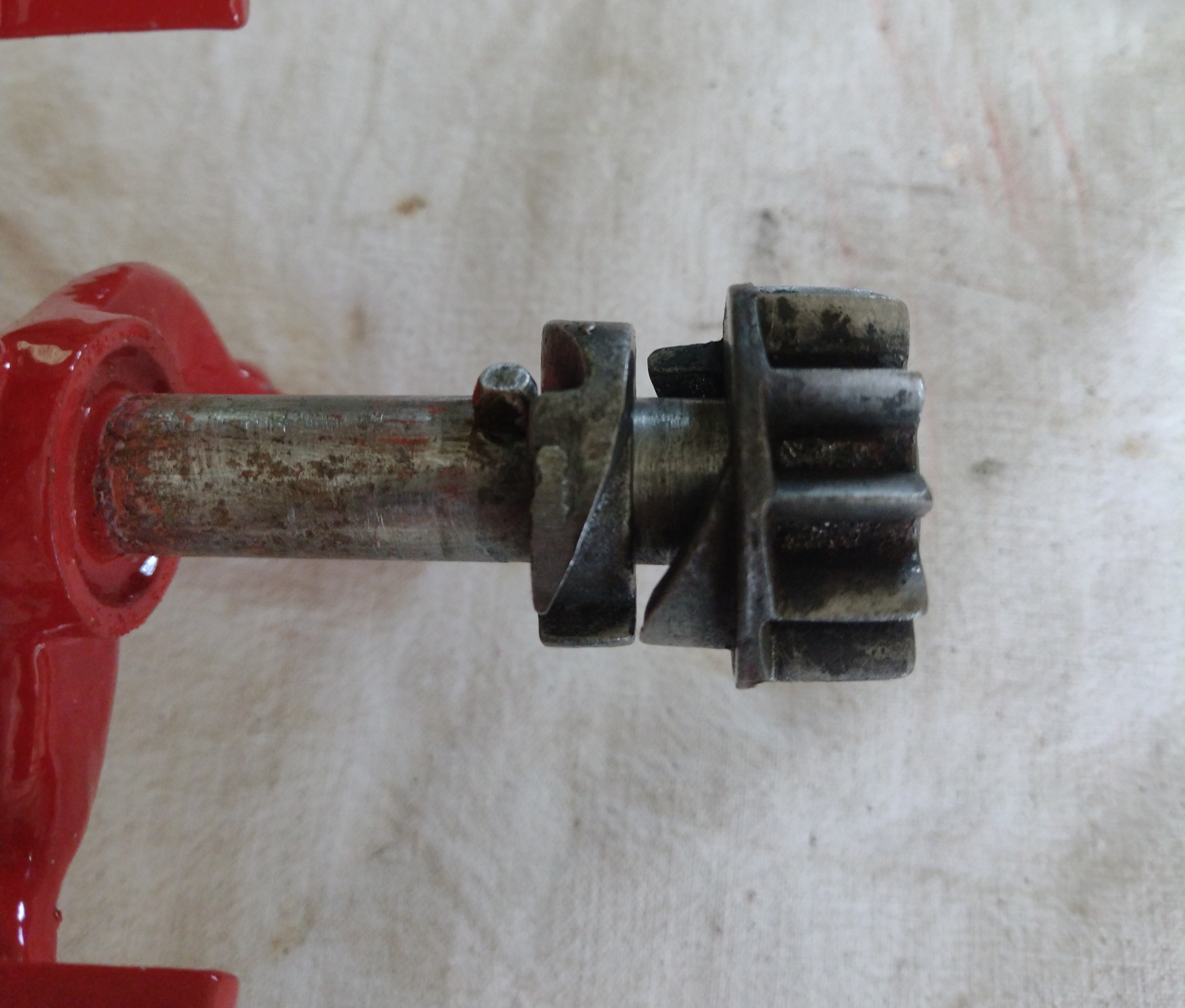
The photo below shows the mechanism in "exploded" view to give a slightly clearer view of the components.
Forums

Thanks Clive, that does seem…
Thanks Clive, that does seem to have similarities. Perhaps the one I have is trying to achieve much the same in terms of not sticking etc although I wasn't aware that was a real problem in the first place.
Incidentally, the side casting carries three patent dates:
July 28 1885 (slightly indistinct but looks like this is right)
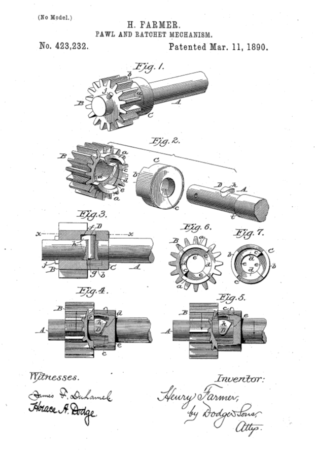
March 11 1890
June 2 1896
Hi Keith, have sent you all…
Hi Keith, have sent you all three patents, the 1885 is H.H. Dille & E.W. McGuire, 1890 H Farmer (The F & N Lawn Mower Co) & 1896 E.W McGuire, an image below from the Farmer patent.
So we can assume your mower is probably a Dille & McGuire?
Many thanks Clive, that does…
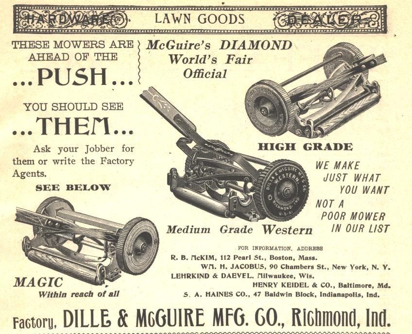
Many thanks Clive, that does look like the mechanism I have on the Magic. Makes sense to assume it's a D&M and a quick online search revealed the image below from 1896.
Hi Keith Came across the…
Hi Keith
Came across the following whilst looking for something else but prompted me to think of your pawls, not exactly the answer but interesting I hope.