A brace of Ransomes Marquis - Restoration
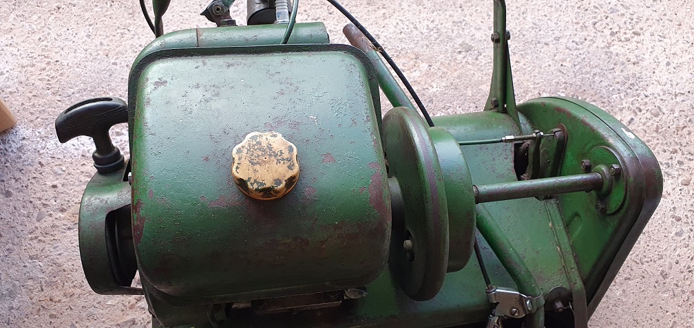
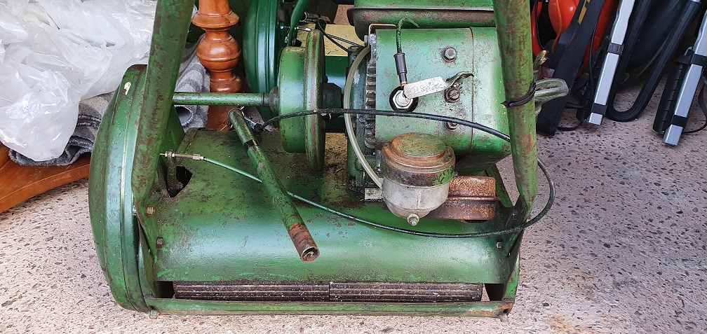
The finish line was in sight for my Atco / Suffolk Super Colt and I wanted to get something lined up for my next project. I spotted a Ransomes Marquis 18" non runner due to no spark (here we go again!), and when I went to look at it, the chap also had a running Marquis which was a slightly newer model, but had a fuel leak at the carb. Needless to say I ended up getting them both in the back of the car, with assistance!, and brought them home.
I'm not going to go to the lengths I went to with the Atco - as good a learning experience as that was, I now want to keep the mowers cosmetically as they are, bar a couple of little touch ups here and there, but overhaul them mechanically to get them both running well. Hopefully I can use one of them as my regular mower as the 18" cut will hopefully make things easier around the garden, and I do like the look of these mowers.
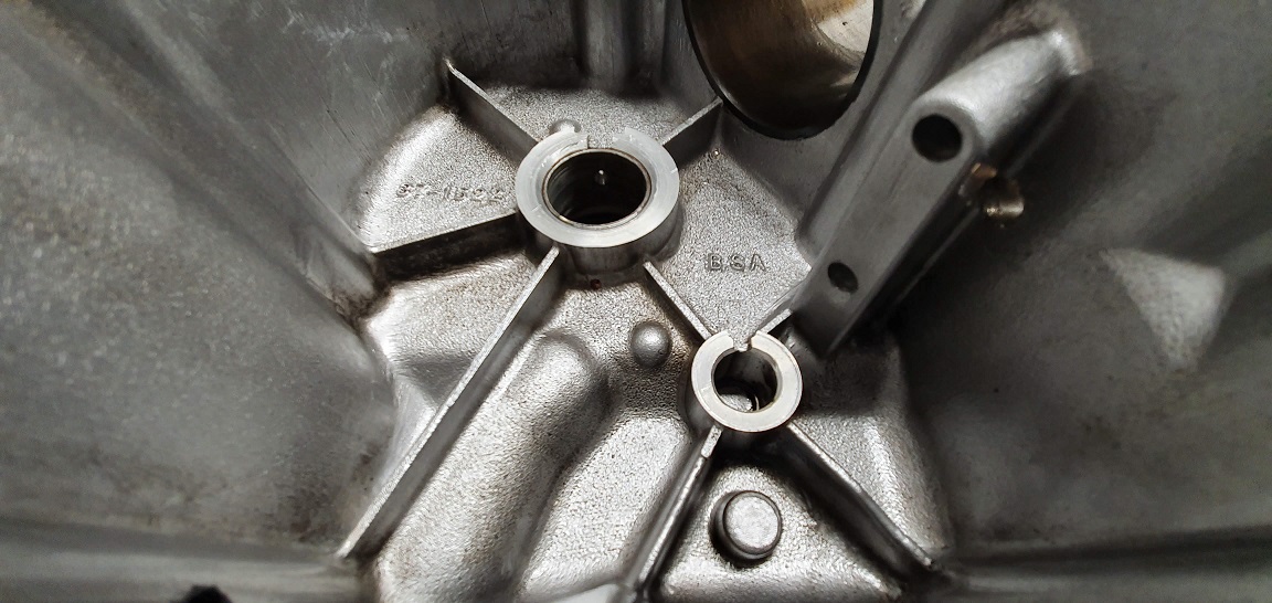
I would like to get an idea of manufacture date for both, and one should be easier as it has the plate on the side which says Mk4, but they both have the same BSA marked F12 Sloper engine
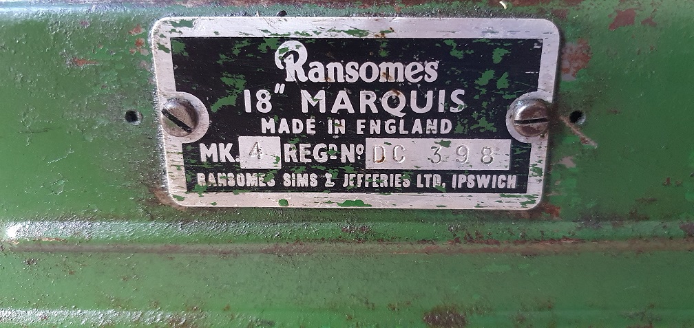
Mower 1 - Ransomes Marquis 18" Mk4 - Reg No. DC 398

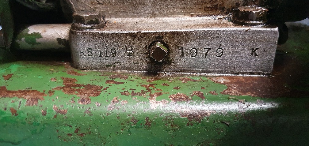
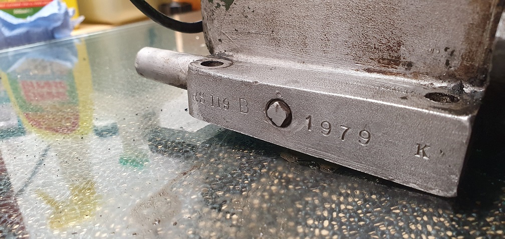
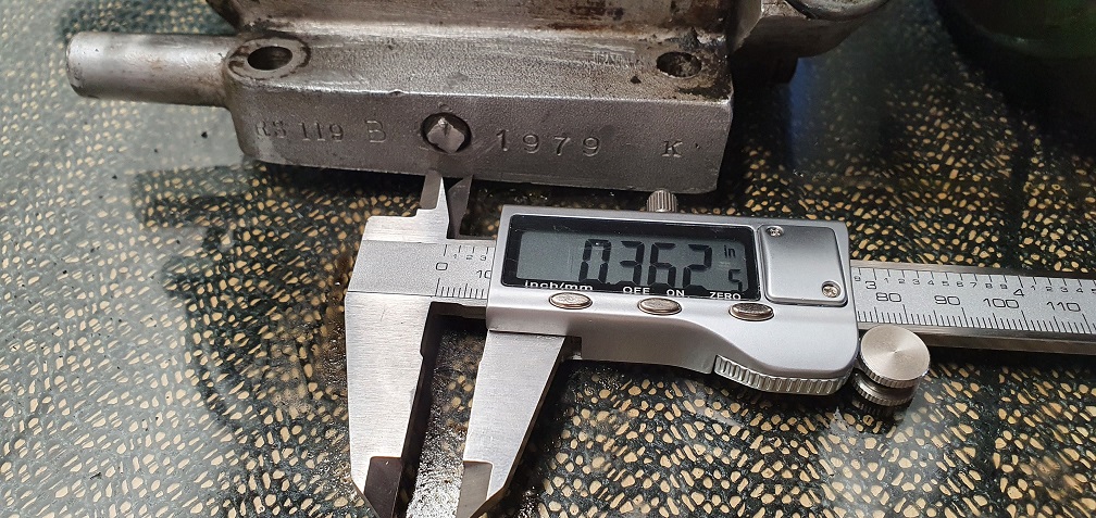
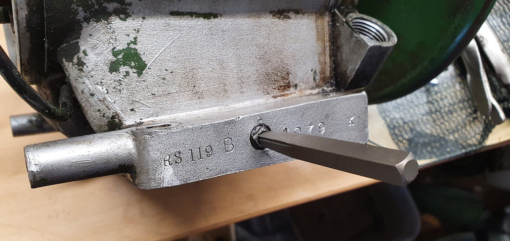
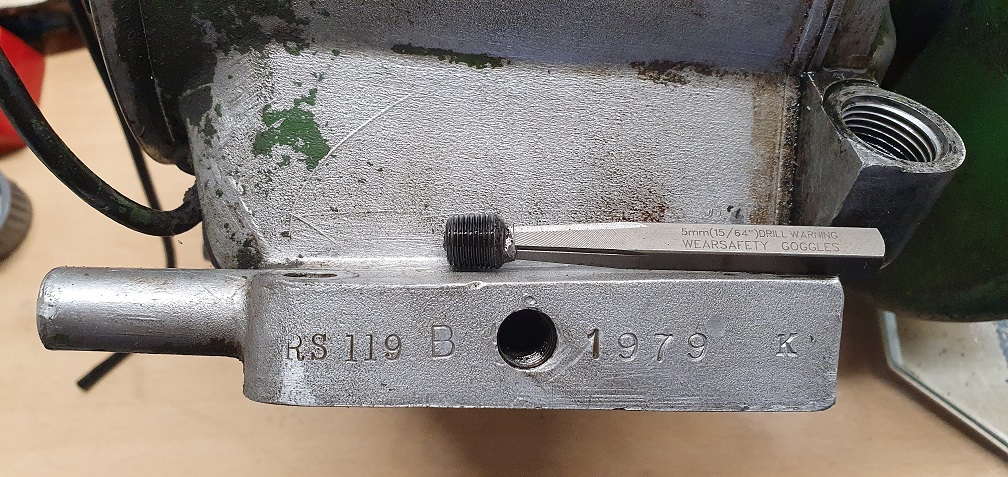
No numbers on the exhaust side of the block like the other mower, however the sump drain plug side has the following - RS 119 B 1979 K
Mower 2 - Ransomes Marquis 18" Mk??- No ID Plate

Forums

Thanks Angus, good to be back
Thanks Angus, good to be back :)
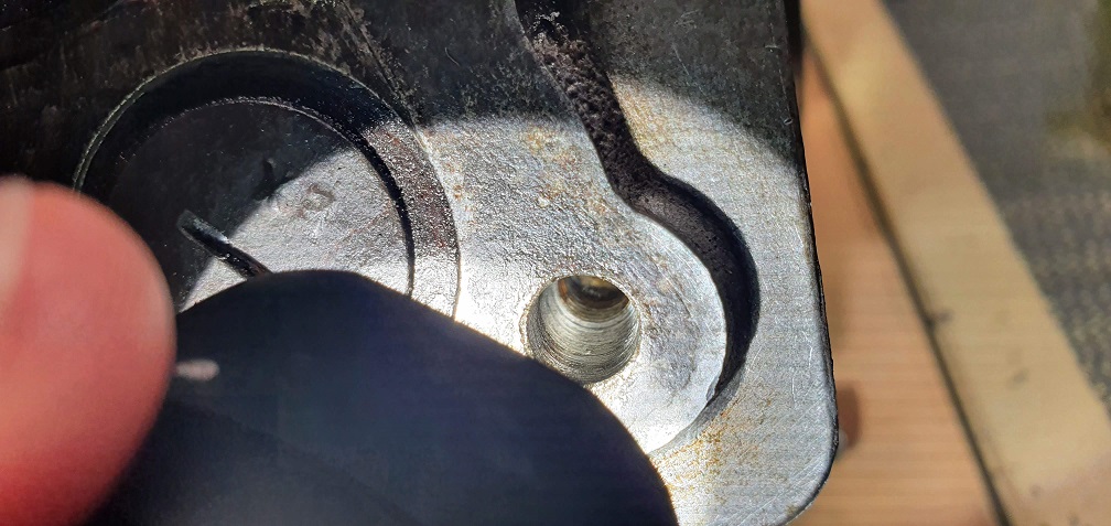
Thank you for the info on the bolt thread, that should make it easier to source one if needed. I would like to remove the stud just to see if it is infact the correct diameter as the original bolt, and was used just for extra length due to overtightening - plus the threads near the top are quite bashed after potentially the wrong size nut was used in the past before being removed. I have a steel rule so will check the block surface and just remove any old gasket material etc, then give the head a once over on some sandpaper on the glass plate, after carbon removal.
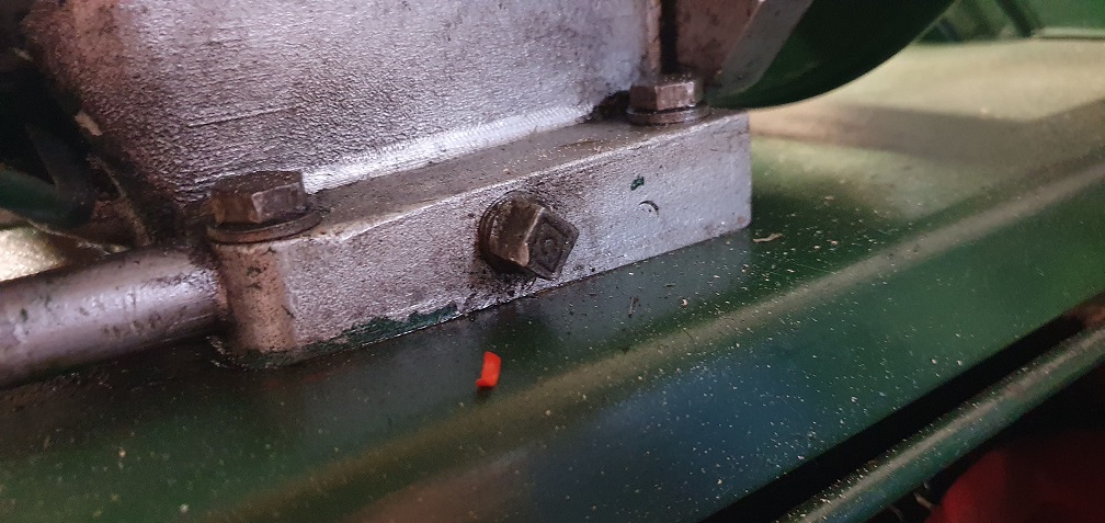
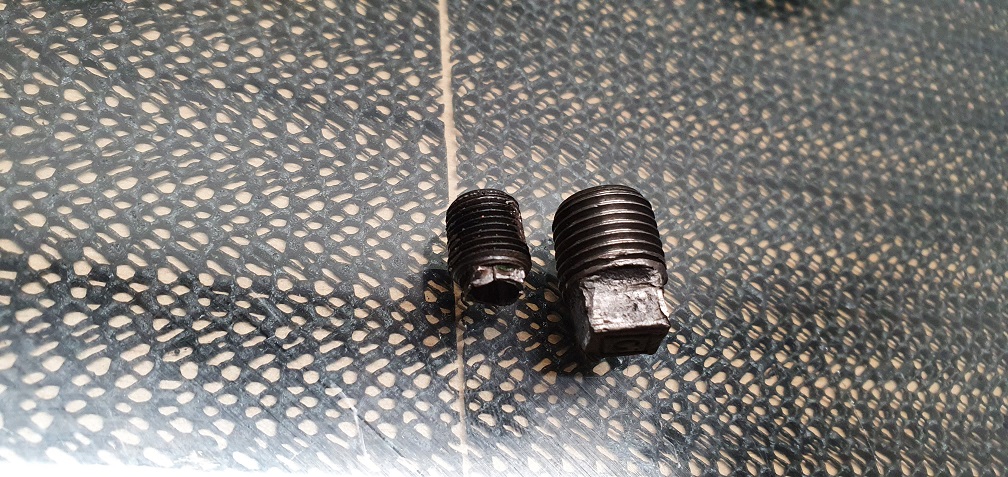
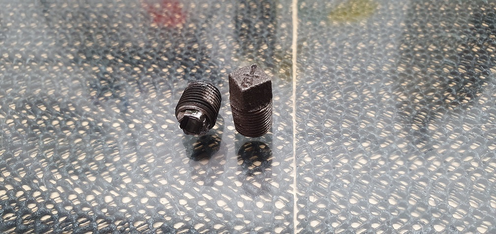
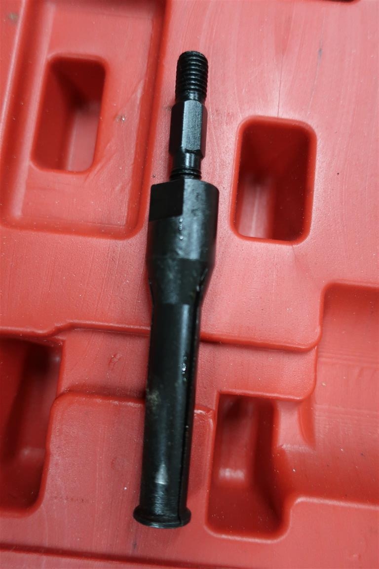
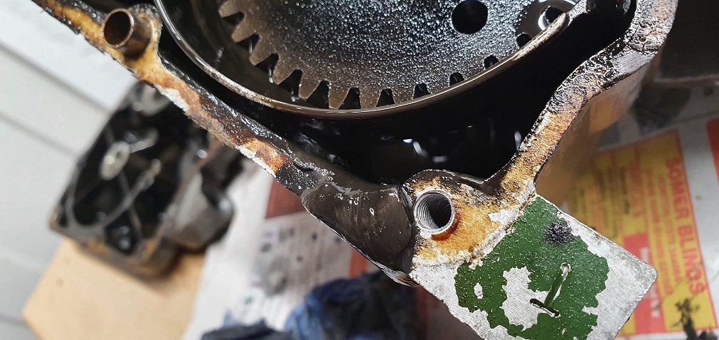
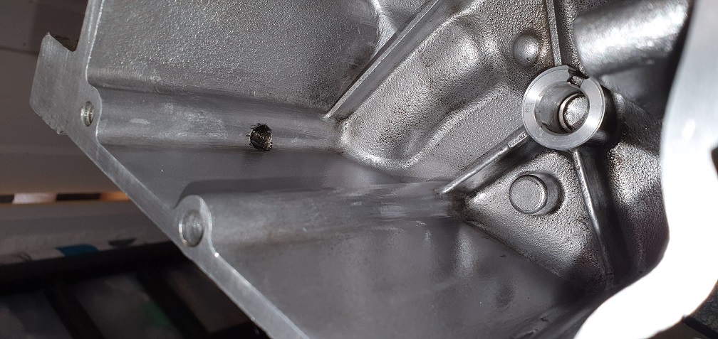
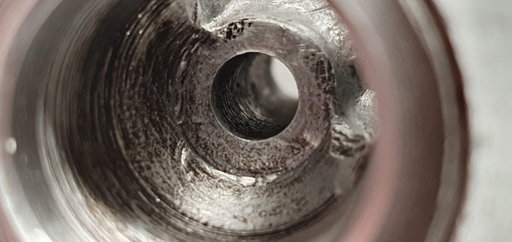
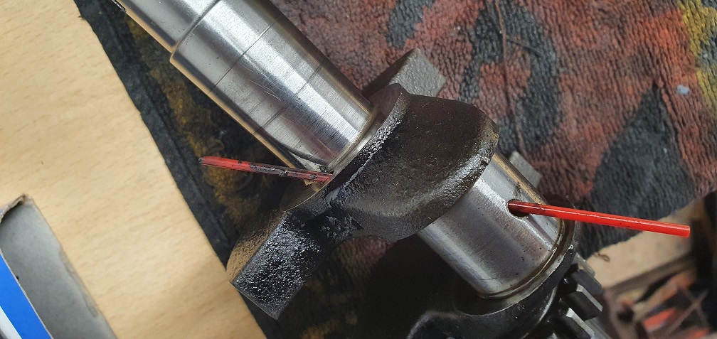
A slight snafu of my own now - i tried to unscrew the oil drain plug and the small square head sheered right off with very little effort :(
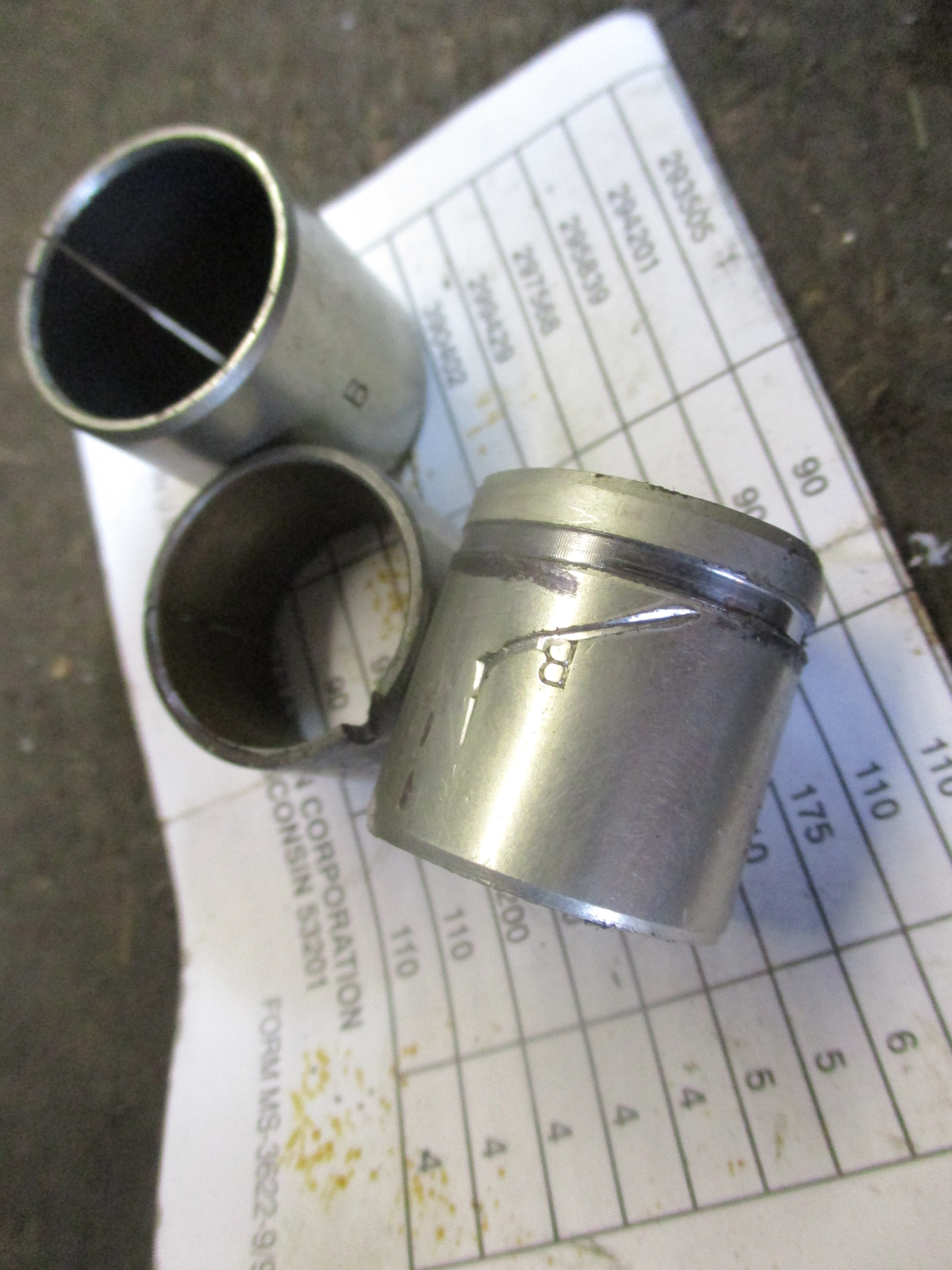
The drain plug on this older engine is considerably smaller than the drain plug on my other sloper engine here:
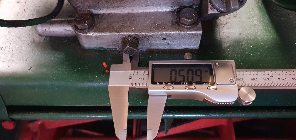
it looks like the broken smaller one is probably a 3/8" thread while the other one is a 1/2" thread
So, what would be the best way forward here - look at trying an easy out /similar bolt extractor to drill into the remains and try to get the threaded part out? Then obviously comes the challenge of finding a replacement drain plug the correct (smaller) size! I see the part number in the F12 parts manual for the drain plug is 86-8771 but I've no idea if this would be the larger or smaller plug. Perhaps some enquiries with Ransomes parts dealers. Oops....
So, what would be the best
So, what would be the best way forward here
I would be inclined to leave it as is, rather than run the risk of creating a bigger problem . Interesting that you have a plug at each end , I don’t think that any of my Slopers has, and a couple of parts books only show one, 87-8771. These days I tend to vacuum the oil out.
Yes after some further
Yes after some further thought, I totally agree - leaving the broken sump plug in place does seem to be the best solution. If i could definitely get hold of the correct size plug then I might be tempted to give the removal a go, but like you say, there are other ways to complete oil changes!
I probably didn't explain very well, but there aren't 2 drain plugs on my engine - I have 2 sloper engines, and the pictures were just to show that they both use a different size drain plug - the broken one has a 3/8" thread and the in tact one on the other sloper engine uses a larger 1/2" thread. Hopefully that one will unscrew without the same issue!
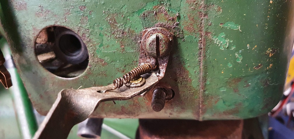
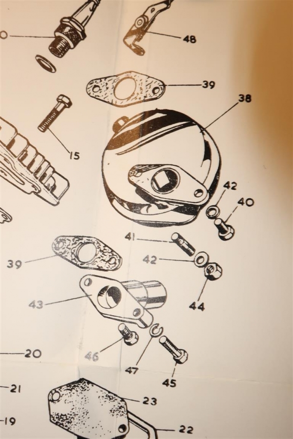
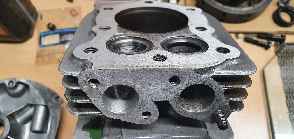
Regarding the exhaust manifold - the parts diagram/list shows one flange bolt and one flange stud/nut, so I believe what I have here is correct, rather than someone fitting a threaded stud in a similar fashion to the head?
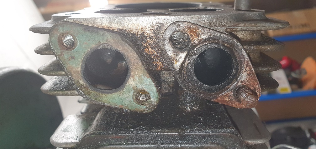
Exhaust, usually one hex head
Exhaust, usually one hex head screw and one stud.
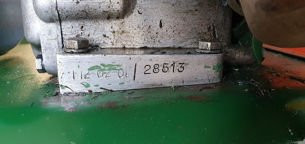
On another tack, your image of the sheared drain plug shows a serial number format that is at odds with any that I can remember seeing. When the weather and mood are conducive, an expedition to the depths of the shed is called for.
Edit. Just realised that the engine serial number is usually at the rear , not the front. Perhaps a previous owner's "fleet" number and date of aquisition.
Thanks for confirmation on
Thanks for confirmation on the exhaust stud.
Regarding the engine block serial number, the rear of that engine doesn't have the regular F12 style serial number on, it's totally blank, so the numbers by the sheared plug are the only engine identification numbers. Could well be like you say, an aquisition date of 1979 and some other reference numbers.
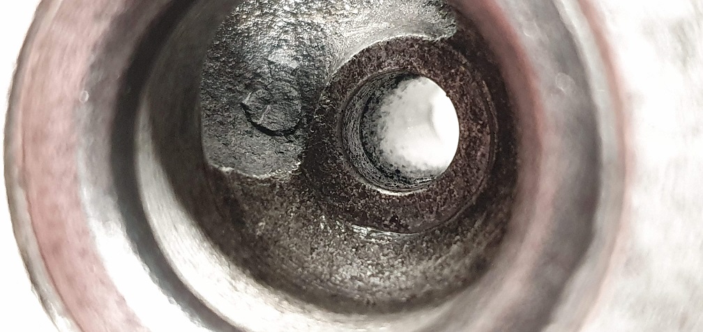
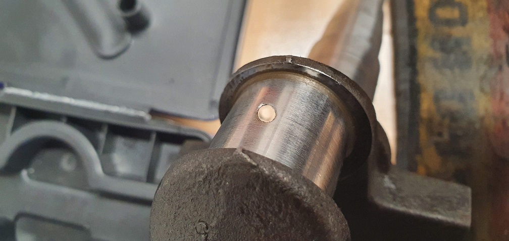
Regarding the drain plug, I removed the in tact larger plug from my other sloper engine and that is a 1/4" BSPT plug, so I imagine the smaller plug on this engine is a 1/8" equivalent thread. Given both sizes of plug are available form various sources I decided to have a go at removing the sheared plug - against better judgement - I blame lockdown for interfering with common sense... I figured it can't be badly seized in the hole as it would likely only be a thread where the tapers interference fit occurs. Thankfully drilling a hole down into the centre of the remainder of the plug, and tapping a extractor down into the hole done the trick, and it came out without a fuss
Showing the size difference between the two drain plugs
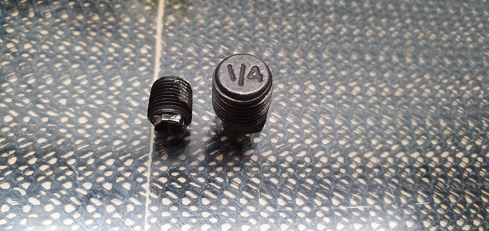
So new drain plug ordered and no damage to the block, phew.
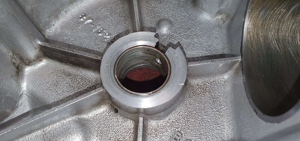
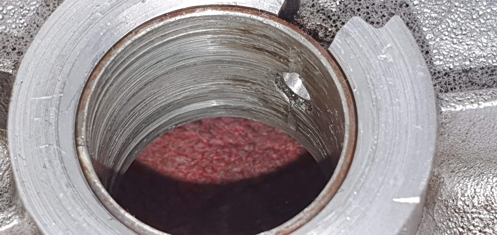
Now, onto that pesky stud in the block - as you can see in an earlier picture, some threads are chewed up on the upper part of the stud - it seems an incorrect nut must have been used in the past to hold the cowling onto the head. Looking at the thread of the stud, it is different to the thread on the head bolts. The same diameter, but the stud looks like a UNF thread as opposed to UNC used on all the head bolts. The head bolts are 5/16" UNC, but the stud looks like 5/16 UNF. Might be that a UNC nut has been used to hold it down in the past, causing the thread damage near the top.
Think I am going to look at removing the stud and seeing that is going on in the hole. Even if it means I still can't use an original head bolt, and have to simply replace the stud with a new stud. I can then use the correct nut for the new thread. Wish me luck.....
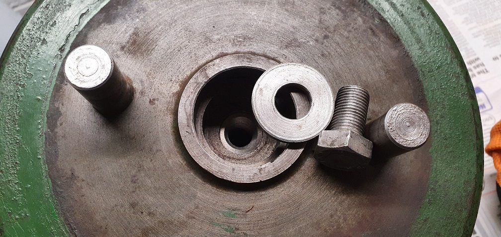
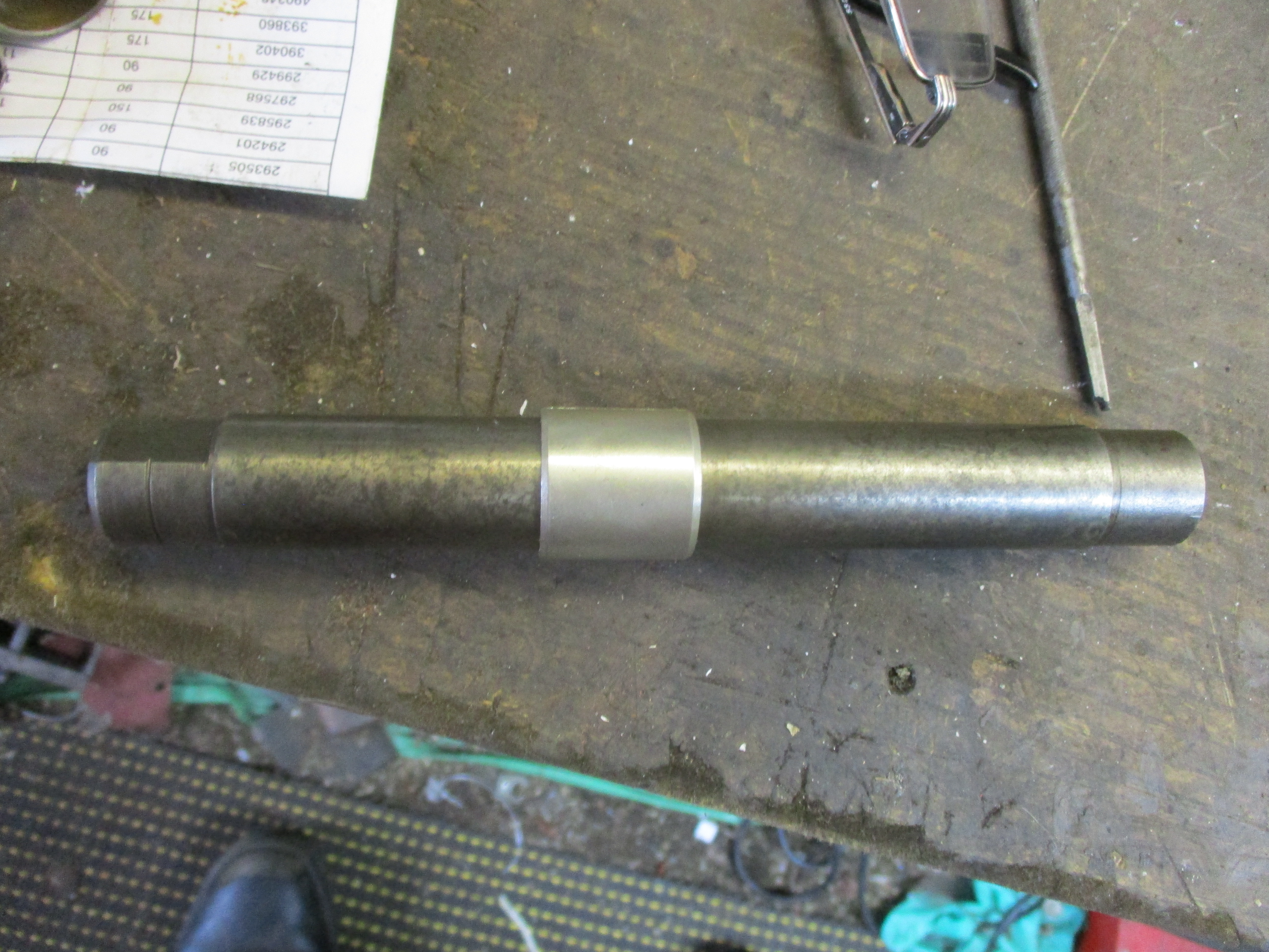
...and out it comes -
...and out it comes - thankfully it didn't put up too much of a fight
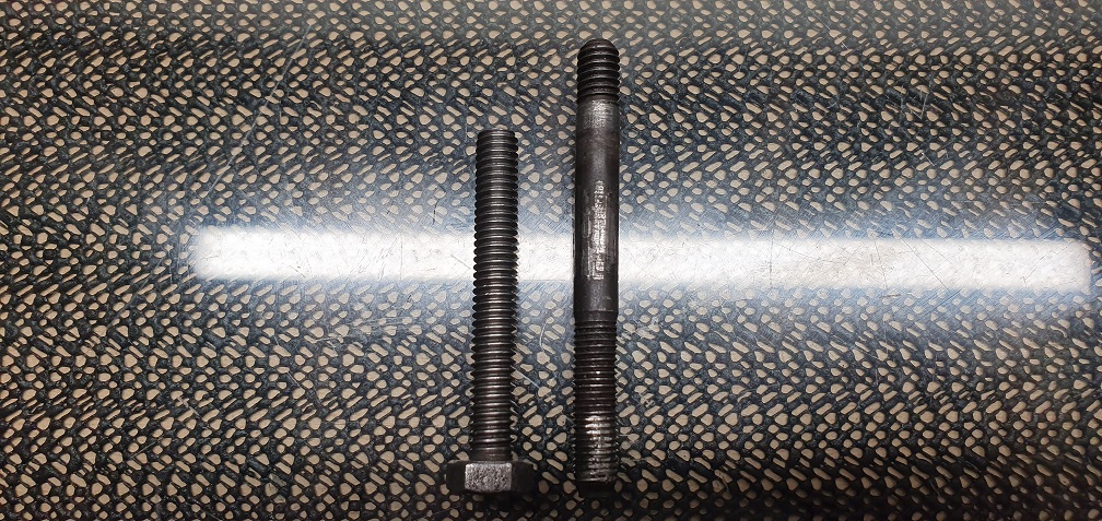
So the bottom part that was engaged with the threads in the block was indeed the original 5/16 UNC (or Whitworth) and strangely the top half appears to be 5/16 UNF. Above is one of the 2 long bolts used on each head for comparison in length. Seems about 3/4" of the original thread in the block is stripped, so the stud was engaging with the remaining lower threads ok. I can hopefully just get a slightly longer 5/16" bolt to replace the stud with - probably 2.75" long rather than 2.25" like above.
New oil drain plug arrived,
New oil drain plug arrived, perfect fit - 1/8 BSPT thread
Next up are the valves.
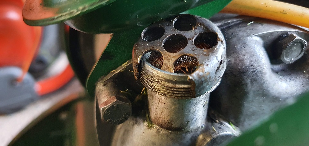
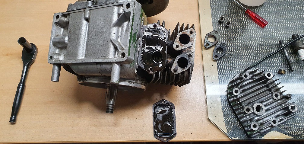
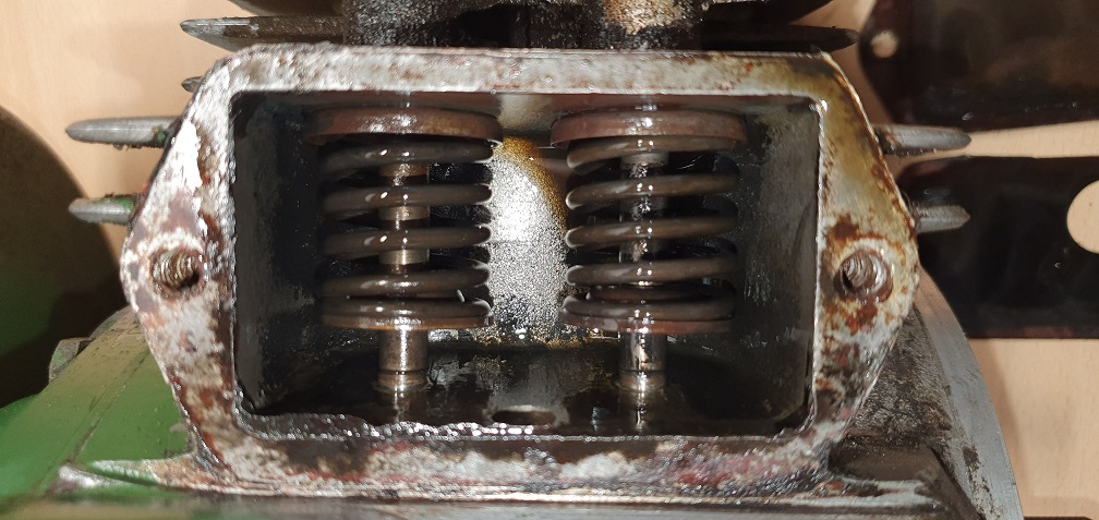
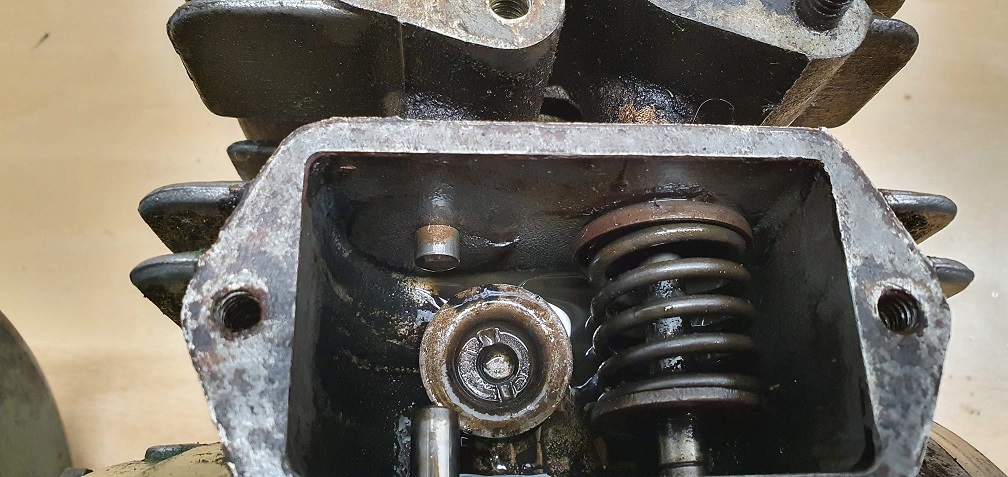
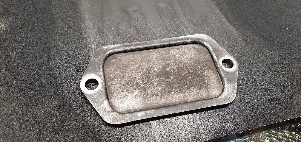
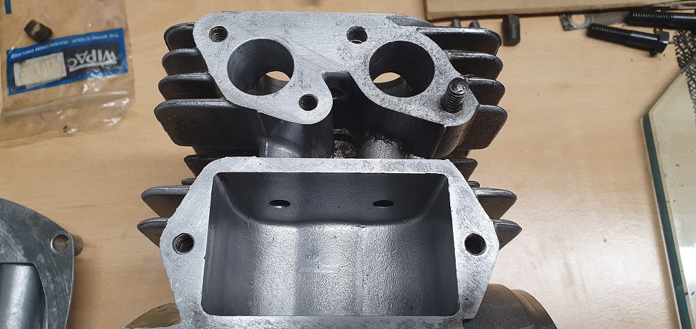
Next up are the valves. Removing the valve chest cover revealed a paper gasket with a hole in - I assume a sort of baffle, although air can't escape as the valve chest cover is fully sealed? My suffolk engine is the only other mower engine I've worked on, and that valve chest cover had a hole in it to allow the crankcase vapour to escape. So when this engine's piston is on the downstroke, where does the positive crankcase pressure go? There is no one way valve in the chest on this engine like there is on the suffolk either. Probably obvious but not to me as I don't have much experience working on engines!
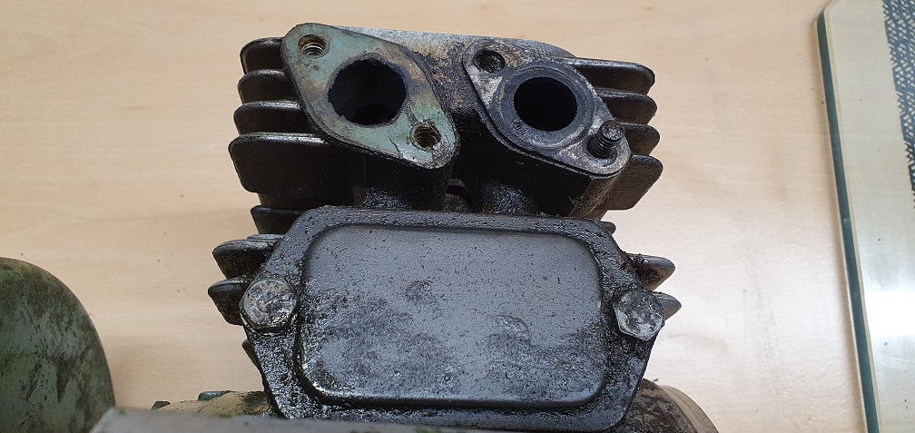
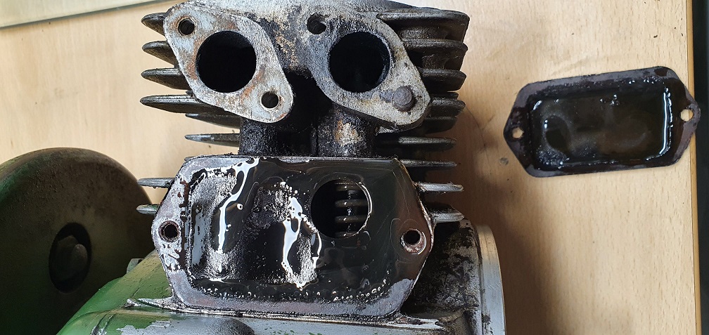
Traces of some sort of Red coloured substance painted on inside the chamber - possibly some sort of gasket sealant?

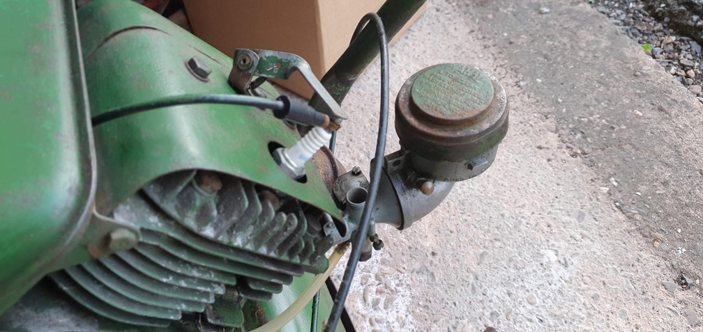
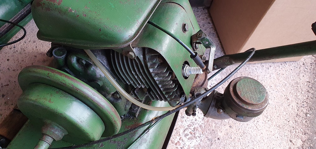
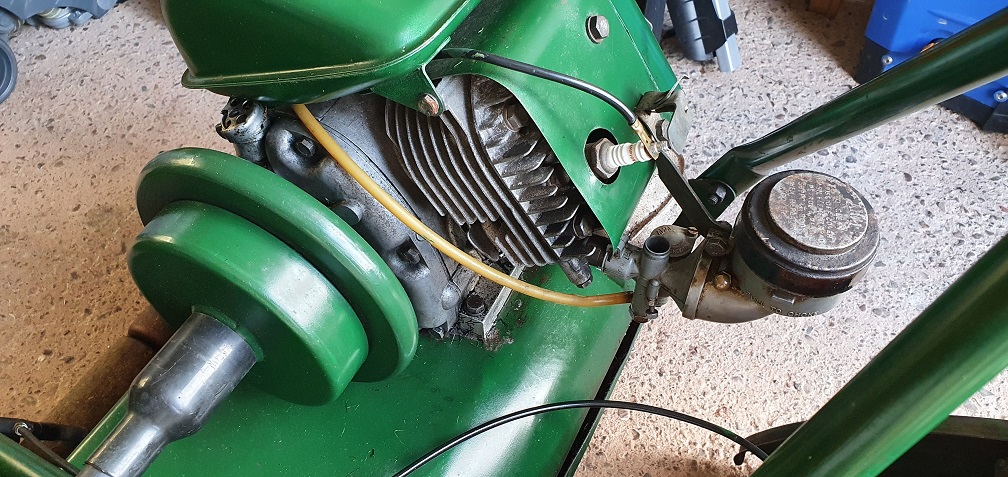
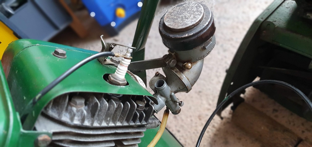
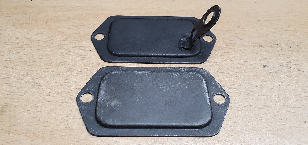
I note my other marquis engine has a 'stand off' attached to the valve chest cover to hold the fuel line(?) - was this an addition/modification to the newer engines does anyone know?
Don't worry about the hole,
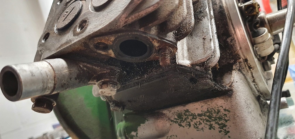
Don't worry about the hole, it is the same gasket as is used on another Villiers engine with a cover mounted breather. Just use a piece of gasket paper to match the cover. Tip - the covers are usually a bit warped / distorted, and time spent rubbing it across some abrasive paper will ensure an oil tight joint. The breather on your engine is at the front, above and to the right of the oil filler.
The "standoff bracket" is to support the correctly routed fuel pipe and I've never seen a Sloper without one; but then I've never seen a Sloper with that "engine number type and location" so unless there's an indication that the bracket has been snapped off, it may be that your engine was a "special build".
Thanks Angus. The gasket set
Thanks Angus. The gasket set that I bought for the engine comes with a new valve chest gasket, but it's a cork type material and just matches the outline of the cover, so i'll use that in place of this one with the hole in, and keep that as a spare, should I ever encounter the other Villiers engine you refer to :) I'll check the cover for flat and give it a rub over the glass plate with some paper at the same time I give the head a quick rub over.
Ah yes, of course the breather is above the oil filler, I even removed the bodged one and replaced it, but to be fair to my memory, that was several months ago......
The valve chest cover definitely hasn't had anything broken off so this one appears to have never had the stand off bracket for the fuel pipe.
Regarding the engine number format, I stumbled across another post on here from another user who had posted up his engine number, and it had the same RS119B XXXX K format as my engine, so perhaps part of the same special batch?
https://www.oldlawnmowerclub.co.uk/forum/history-and-technical/technica…
I’ve never seen a Sloper with
I’ve never seen a Sloper with a cork valve chest gasket, but I’ve recently done two 150cc Light weights and the sets for them had very flimsy “ outline” valve chest gaskets. So flimsy that I gave up trying to get them to seal and made more substantial gasket material ones. It’s my guess that you may have a pattern part gasket set but the two screw fixing of the Sloper is easier to manage than the spring clip of the Lightweight, but beware of overtightening and distorting the cover.
To the best of my knowledge, the best person to ask about the serial number would be Paul Child at Meetens.
Thanks Angus. The gasket set
Thanks Angus. The gasket set was ordered from Villiersparts and you can see the cork gasket here
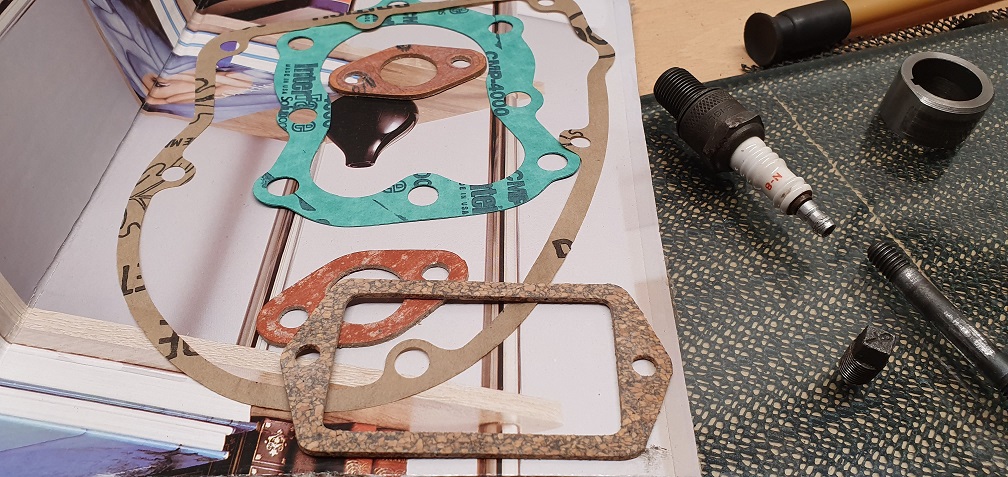
Once I've cleaned up the cover plate I'll try fitting this one and see how it goes - keeping the original just in case the cork one doesn't work very well. I've also got some sheets of gasket material that I bought when doing the suffolk, of various thickness, should I need to make one.
Paul at Meetens was able to identify my engine starting with number RS119B as an "early model - late 50's to early 60's", and I've found some pictures on the internet of another similar engine with the small 1/8 drain plug and serial number starting RS119B here:
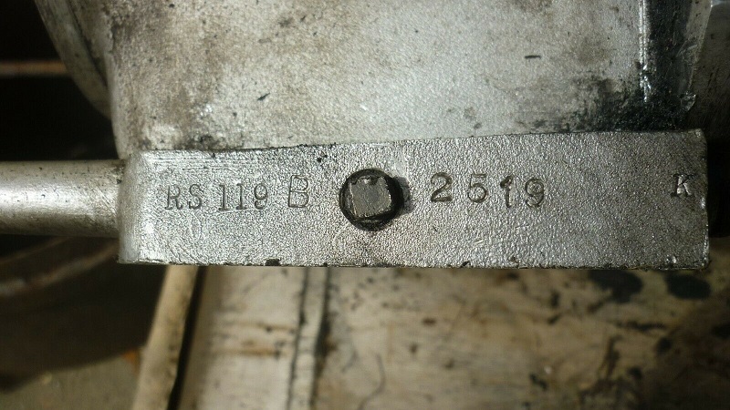
So perhaps the very early models used this numbering format before they changed to the serial number on the back, which uses the format starting with 'F12'?
That valve chest gasket looks
That valve chest gasket looks fit for purpose and a lot more substantial than the ones for the Villiers Lightweight models. Interesting Paul has identified your engine number identifies it as an early model. I have a couple of engines with the cast BSA logotype but they have the “conventional” serial number format, so presumably they are later ones. No one has remarked that the 119 almost certainly relates to the cc of the engine. Next question - the date when BSA were acquired by Villiers and was there an instant change from the BSA logo or did it continue until stock was used up or the tooling wore out and was remade without the logo.The other thing that you may have noticed is that there was a change in the method of securing the lower valve spring retainers, from “ horseshoe” to pin.
,
Removing the valves yesterday
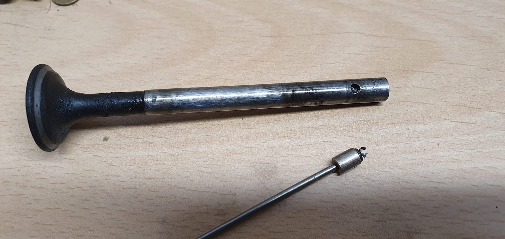
Removing the valves yesterday - the intake vale was quite stiff to remove through the valve guide - it looks like the hole in the valve stem where the retaining pin locates is slightly raised at the edges, so I had to carefully flatten this off before I could extract the valve
Also, some metal shavings were in the valve chest area - possibly from wear on the spring seat where the pin has worn away at the underside (see picture above)?
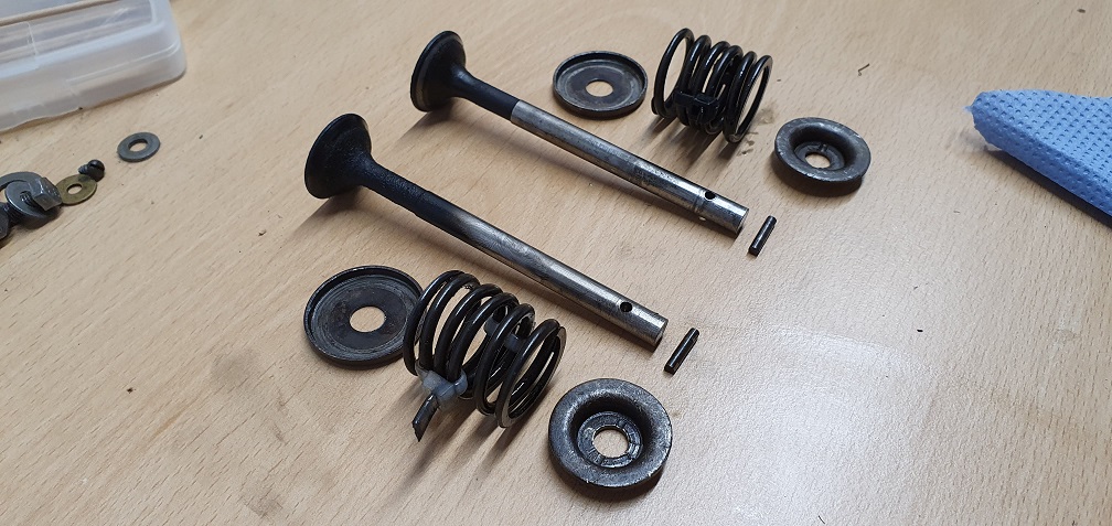
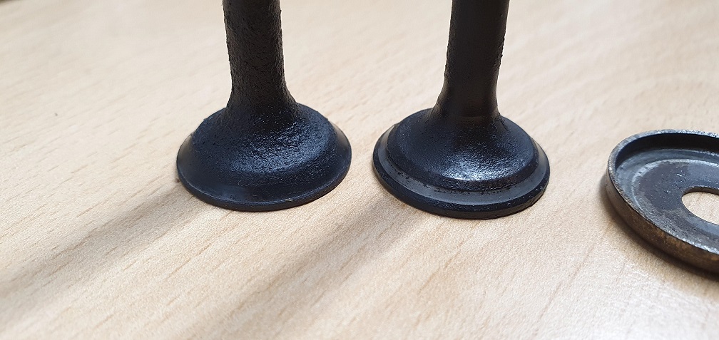
valves don't appear to be too bad, so hopefully just a clean up and lap them in - the inlet valve seat looks pretty good and hopefully the exhaust seat will clean up ok before lapping
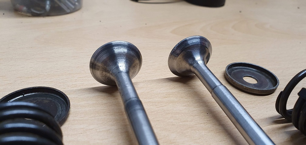
One thing I have noticed though is that there is a 'substantial' gap around the exhaust valve stem when it's in it's guide in the block - shining a torch into the valve chest recess there is a lot of light, and you can really wobble the valve stem
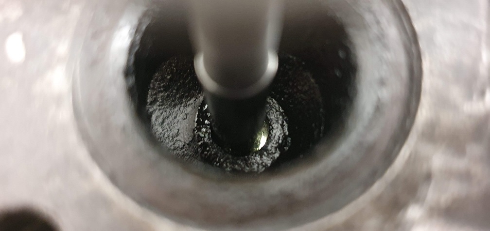
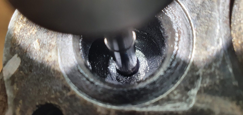
I have seen that you can get oversized valves, but I doubt even an oversized valve would take up the room around the exhaust valve stem. What are the likely issues when running an engine like this - will it just run a bit smokey? As long as the valve face makes good contact with the seat, I assume compression will be unaffected (assuming piston rings are good etc)?
Valve stem / guide wear. To
Valve stem / guide wear. To be expected on an old engine and it will possibly smoke a bit. Back in the day it would be a normal part of the reconditioning process to ream the guide to the next oversize stem having checked the guide with a “go, no go” gauge. New standard guides were available the would usually be tight and were reamed for use with new standard stem valves.
Looking at your image, I’m guessing that a new standard stem would sill rattle around a bit - have you measured yours with a mic or vernier? I had an F15 a while back on which the stems were so worn that I could see that they were oval without needing to measure. Amazingly the engine started second pull and ran with no visible smoke and is still powering a Ransomes Twenty Four.
I wonder if valve guides were
I wonder if valve guides were fitted to later model F12 blocks perhaps? The guides are just holes in the block on this engine, so none to remove/replace. I suppose you could ream the holes to accept guides and insert via freezing guides/heating block, but probably only worth going to that extent if the engine runs really badly and/or smokes a lot.
Measuring the valve steams, they are surprisingly both in very good shape along the length of the moving area, and are spot on with the book figures
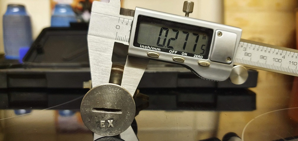
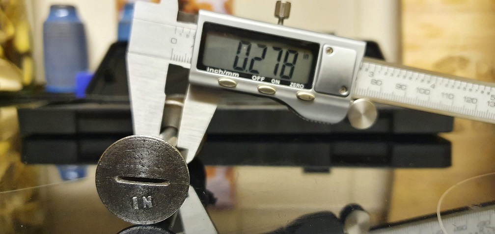
The oversized valves available according to the parts list, were +0.010" so this definitely wouldn't make up the difference in the exhaust guide space. I think I'll just look at cleaning out the ports and lapping the valves and see how it runs when back together.
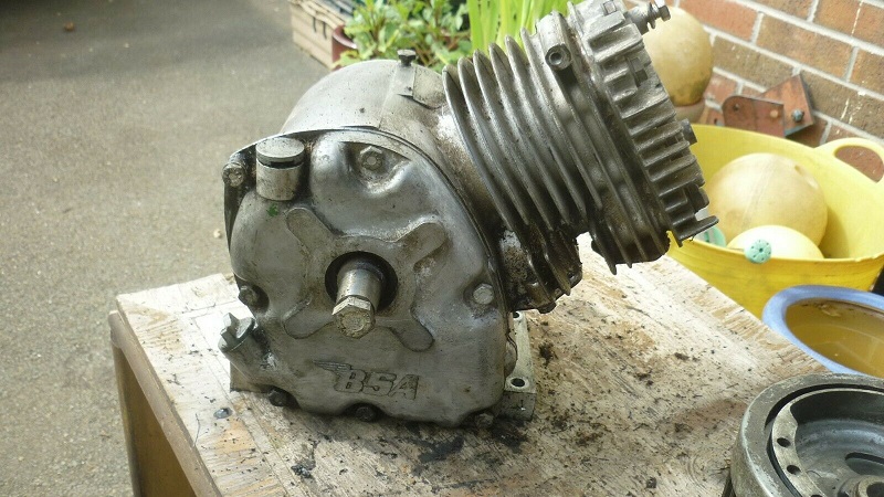
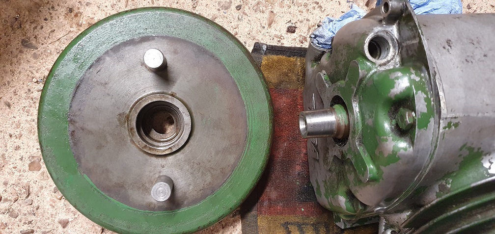
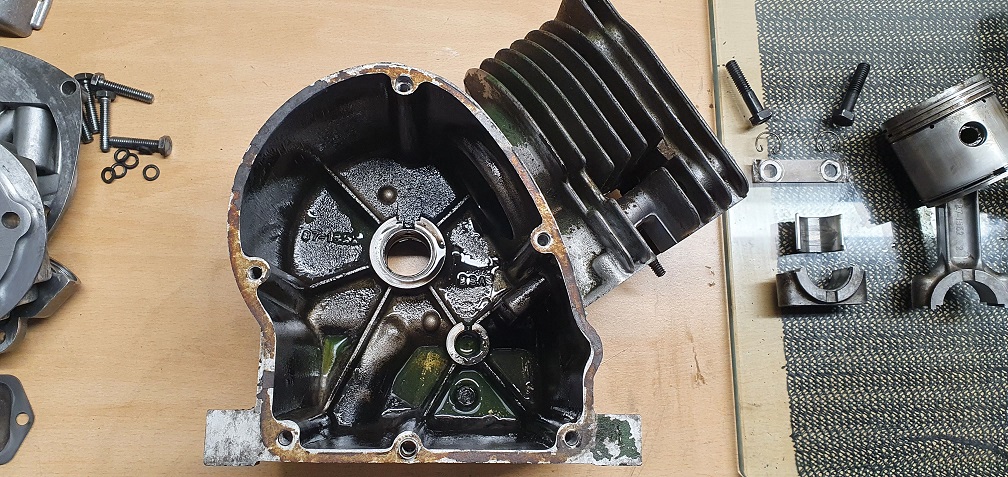
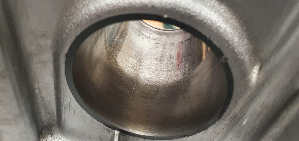
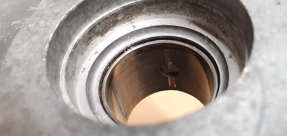
I want to flush the block out due to the drained oil being like treacle, plus the metal shavings I found in the valve chest. With no removable sump like the Suffolk engine, this looks like I am going to have to remove the clutch shoes and flywheel
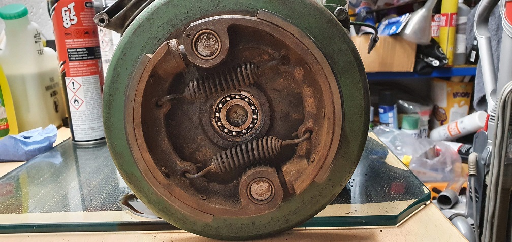
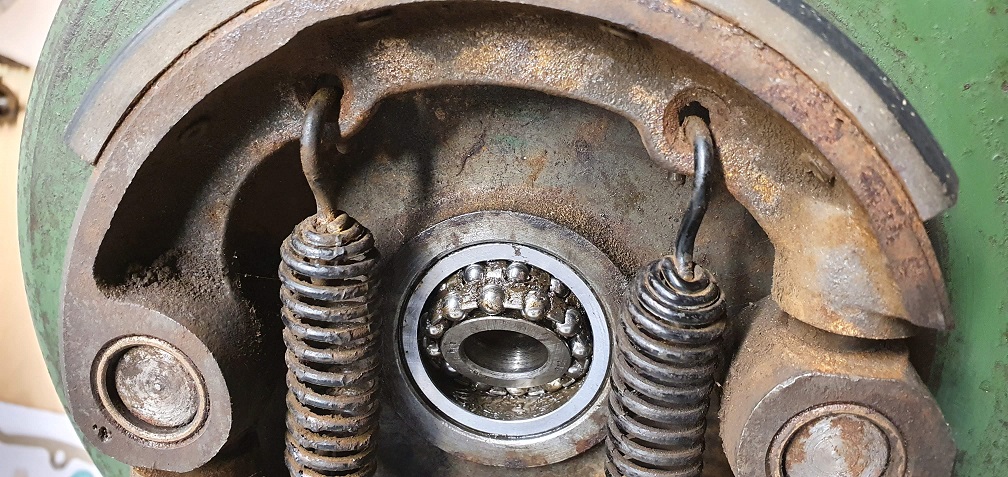
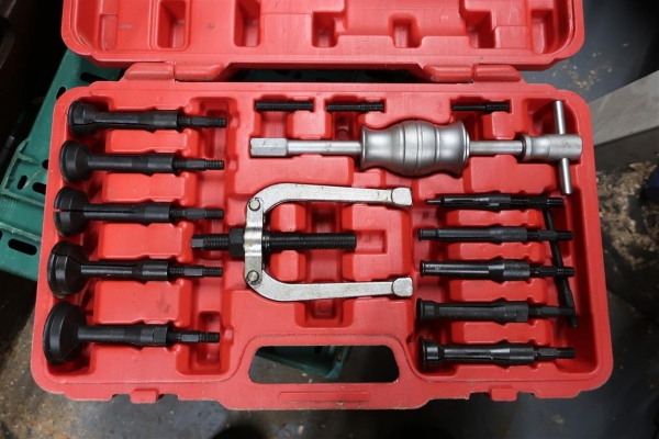
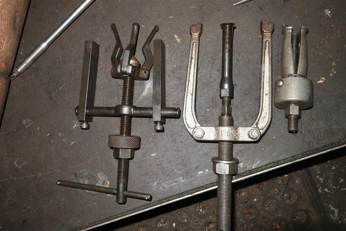
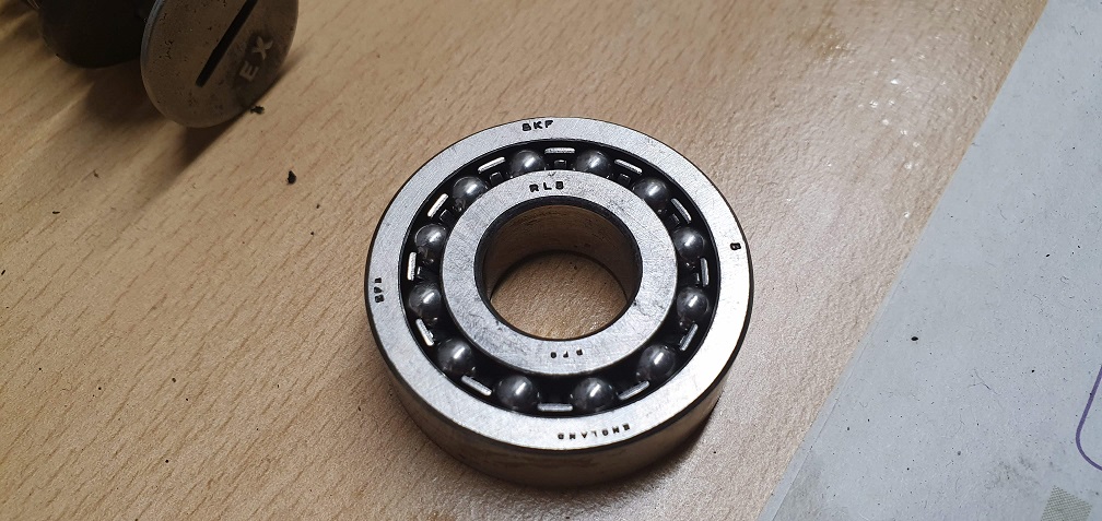
The self aligning RL5 bearing is in good condition with plenty of grease, however I've not removed a bearing like this before - the hole is too small to get my 2 legged puller through, so it looks like some sort of internal bearing puller is required. Perhaps one that grips hold of the inner race internally? I've read that the flywheel is a taper fit onto the crankshaft, and partially unscrewing the bolt behind this bearing is a good idea to prevent the flywheel falling during removal. I believe it was a post by Wristpin that also mentioned about supporting the flywheel boss on something solid, then using a large drift and striking the boss on the opposite side to the support in order to work the flywheel free. So removing this bearing is the key to further progress, hopefully I can get hold of the necessary tool.
Valve guides. I've got
Valve guides. I've got several F12 parts books and they all show guides; but they are all branded Villiers so the lack of guides may go with the BSA branding and the "strange" serial numbers. I've worked on many BSA branded engines over the years and a couple quite recently and not noticed the lack of guides but perhaps I was on autopilot.
Spigot bearing removal. Yes it does need a specific clawed puller to remove it without damaging it . There are pullers that fit between the inner and outer races but they involve breaking through the bearing cage.
Clutch flywheel removal. Yes again just slacken off the hex head centre screw to retain it when it frees off the taper. Support the flywheel and hit the sloping face of the boss with a drift and a lump hammer to shock it loose. Supporting the flywheel avoids the possible risk of causing shock damage to the crankshaft main bearing.
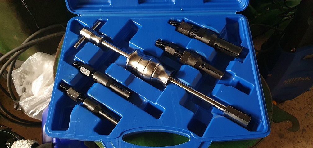
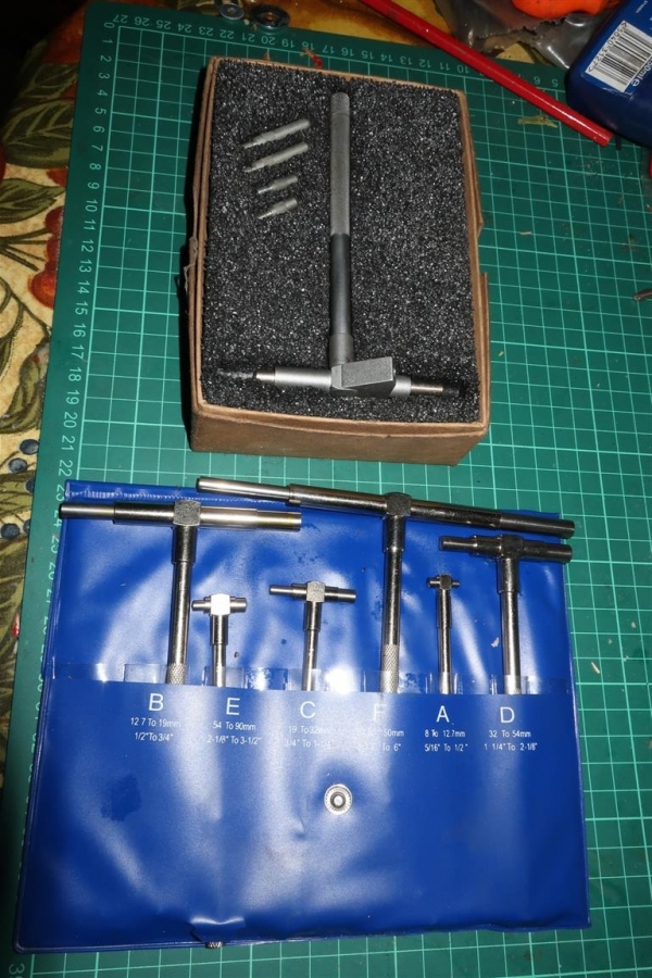
Assorted internal bearing pullers.
Ah I see, thanks very much
Ah I see, thanks very much that's very helpful. Next day delivery is a wonderful thing... Just a small kit, but covers the size I need for now
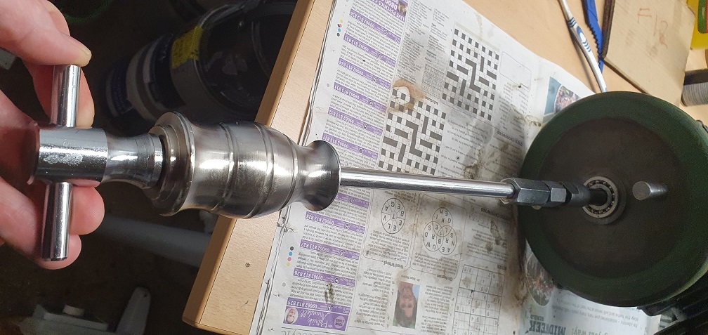
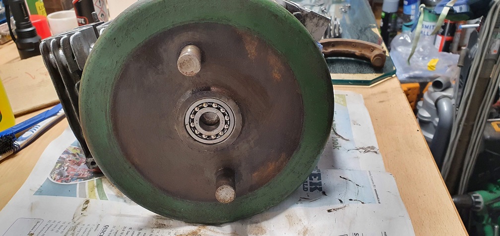
and 2 minutes later out it comes
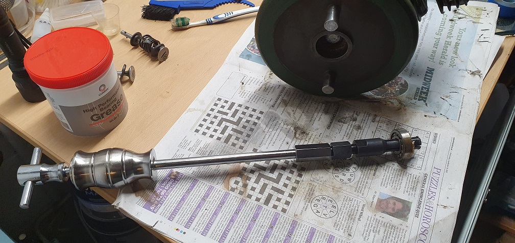
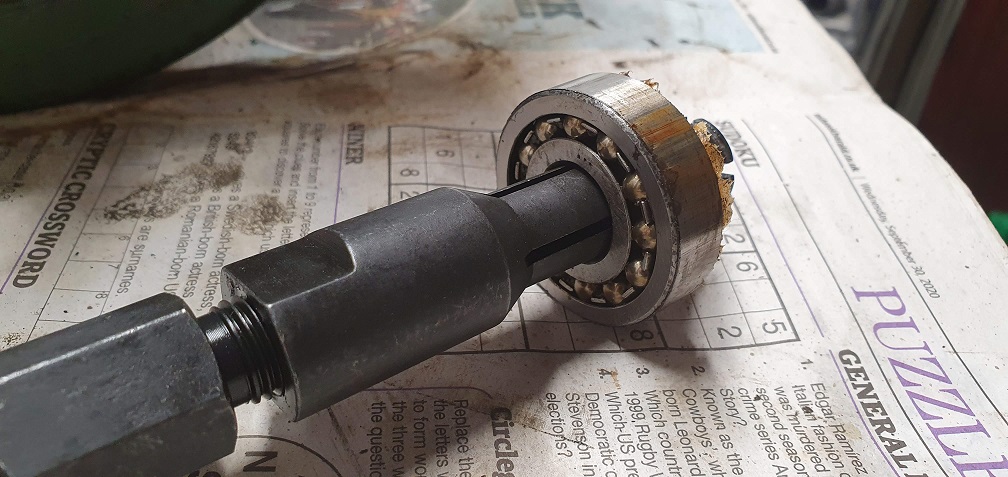
Flushed all the old grease, some of which was pretty solid/dry, with a petrol bath and checked the bearing over for damage, all looks good and ready to be repacked with fresh grease upon reassembly
There appears to be a 'moat' of orange grease surrounding the flywheel retaining bolt
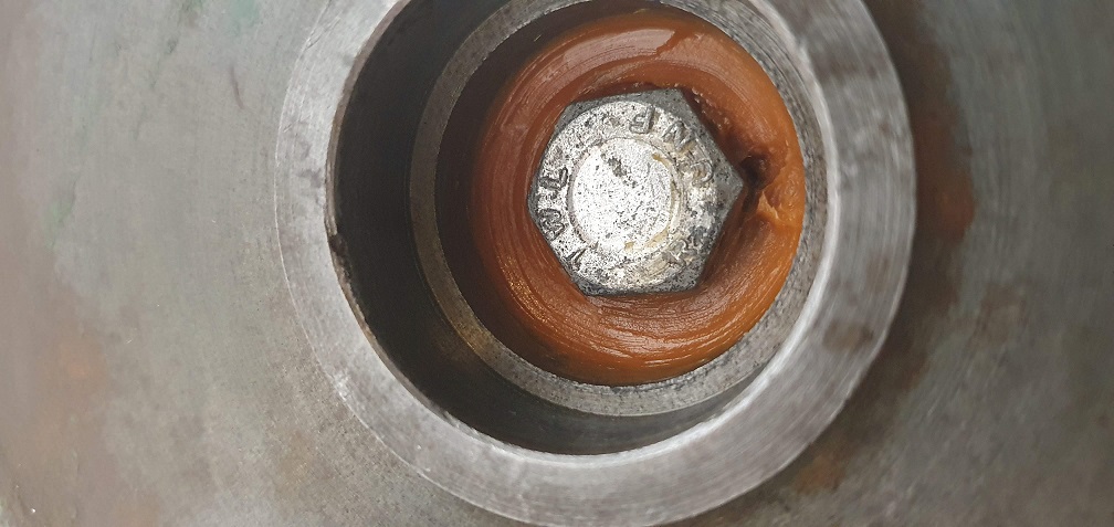
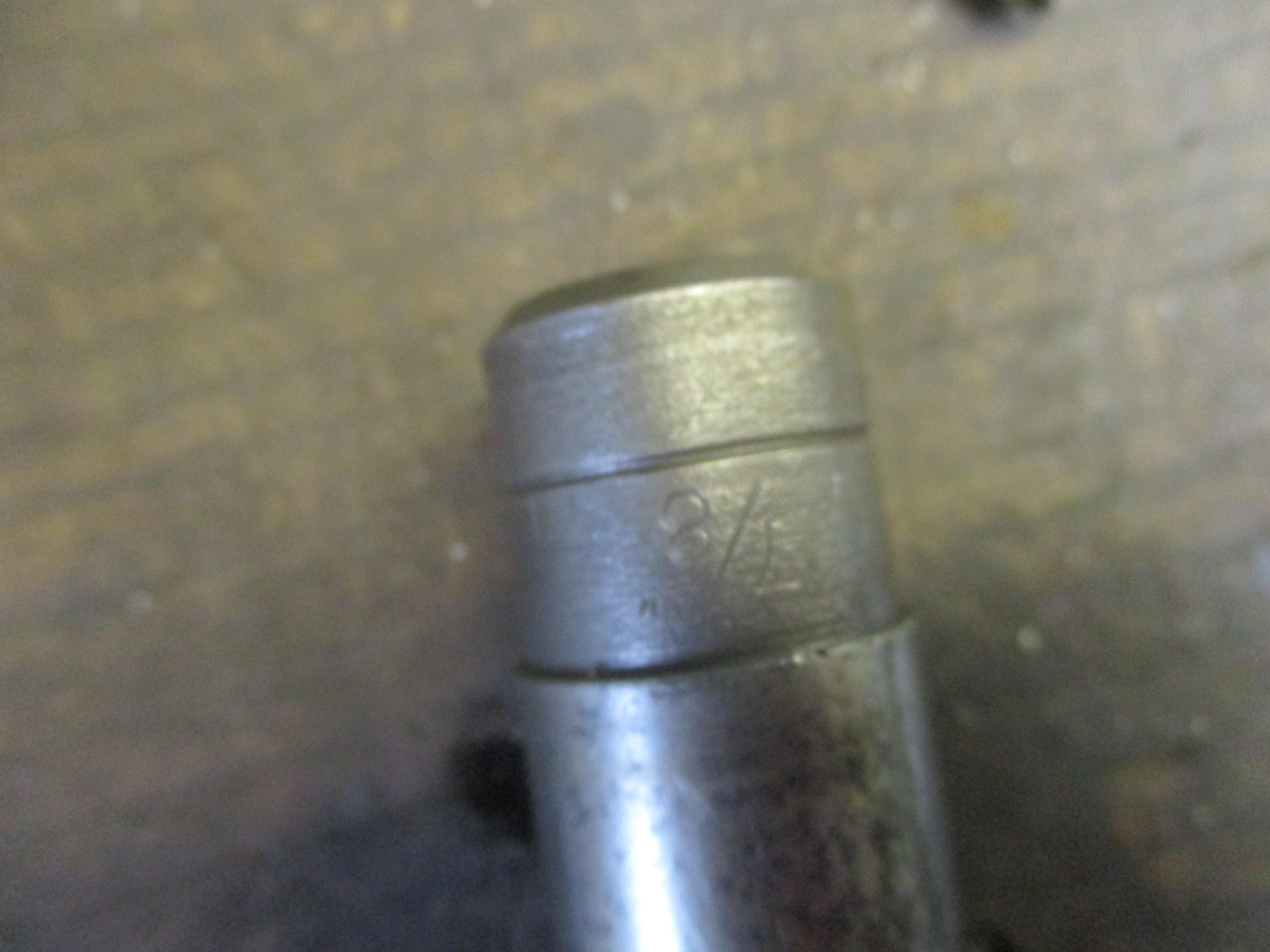
So the bolt is UNF, and a quick test with a socket shows its 3/4" - however is this a regular right hand thread so anti-clockwise to undo?
Regarding the valve guides, I'll whip the head off and remove the valves from my second sloper engine which has the 'newer' serial number format, although still has the BSA logo, and see if there are valve guides in that block and report back
Flywheel retaining screw.
Flywheel retaining screw. Conventional right hand thread.
Bearing removal . A bit late now and probably a bit anal but I would use the legged puller rather than the slide hammer on a bearing that I’m going to reuse . Why? Using the slide hammer to take the impact from the inner race via the balls to the outer, could result in peening of the races to the detriment of bearing life.
Thank you, I'll get started
Thank you, I'll get started on the screw removal! As for the bearing, I did wonder about any possible damage from the slide impacts, however given how easily the bearing came out, with no corrosion of the outer race, the fairly gentle taps to knock it free hopefully won't have created any damage. Certainly nothing visible and everything feels smooth when rotating. Saying that, what I may do is replace the bearing and just keep this either as a spare, or keep the outer race for tapping the new bearing into place (If I don't have a suitable sized socket). Will try to pick up a small legged puller for future use at some point!
Sockets have all sorts of
Sockets have all sorts of uses other than the obvious! That bearing should be the same as the two cutting cylinder bearings , one of which is in a blind carrier so your extractor could be useful. However you may find that a previous repairer has drilled a couple of small diameter holes in the back of the carrier so that the bearing may be tapped out with a small parallel punch.
Yes I have a few dedicated
Yes I have a few dedicated sockets which are set aside for alternative tasks!
Creating the necessary anvil here is proving a challenge. I have the hammer and the drift but can't seem to find something suitable that will fit in the gap between the flywheel and block to rest the flywheel boss on. If I can't create somethign suitable, would a large reach (200mm ish) 3 leg puller do the necessary instead?
Useful info for the cylinder bearings, i'll keep that in mind for when i reach those!
Flywheel removal. Just
Flywheel removal. Just something solid with no bounce to rest the rim of the flywheel on with that side of the crankcase just clear of the bench/ground will be fine .
Taper fits can be quite reluctant to let go, but a bit of puller tension with a few sharp taps outwards on the flywheel rim may work. I know that some people do similar with engine flywheels , which is fine until they do it on one with a charging system and find that the impact has dislodged the Ferrite magnets inside the flywheel rim.
While we are on about avoiding oops moments, if you are ever working on a small engine with a starter motor, the chances are that it has a ring of ferrite magnet bonded to the inner wall of the cylindrical motor body. It won’t take kindly to being squeezed in the vice while you change the pinion or bendix. Operation successful but the patient died.
I love my very cheaply bought
I love my very cheaply bought set of Sykes-Pickavant 10 ton hydraulic pullers, I paid £7 for a whole lot that included only one hydro main central part, I've bought two more since, plus two outer bearing 'split cup' type accesories to go with that lot, I have a wind up type puller and slide hammer for blind bearings, but have not used either as much as the outer types, heat is a big help too. Chap at the recycle centre didn't know what he was selling of course, when I told him after the sale, his face was a picture!
I noticed that some say WD40 is only a water repellant spray, but if you buy the 1 gallon plastic containers with free hand pump, it clearly states on the cardboard packaging that it is also a lubricant, 'squeak silencer' and rust inhibitor too, etcetera. I use about a gallon a year, or did when I was in business, some years even more than that.
I noticed that some say WD40 is only a water repellant spray, but if you buy the 1 gallon plastic containers with free hand pump, it clearly states on the cardboard packaging that it is also a lubricant, 'squeak silencer' and rust inhibitor too, etcetera. I use about a gallon a year, or did when I was in business, some years even more than that.
Speak as you find. The clue is in the name, Water Dispersant 40; allegedly the 40th formulation they tried . I’m no fan of the stuff other than drying off damp electrics, certainly not as a penetrating oil or thread lubricant. I’ve heard it said that the best thing about it is their publicity.
My preferences are Plus Gas as a penetrating fluid and Duck Oil or GT85 as a general purpose maintenance spray.
I've used WD40 over the years
I've used WD40 over the years and it certainly has it's uses. It can work to a degree, although unintended, in lieu of alternative substances, but I prefer to use plus gas for stubborn things and have also used GT85 for many years, mainly for bike or general maintenance.
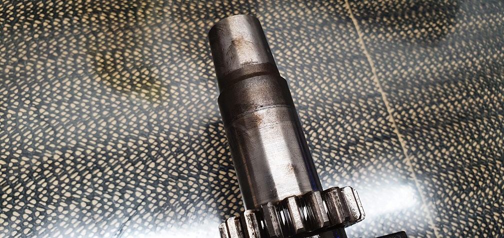
So a few hefty strikes on the drift and the taper broke and the flywheel could be removed. Surprised just how heavy the flywheel is - does this weight act as a sort of governor system to limit how high the F12 engine can rev?
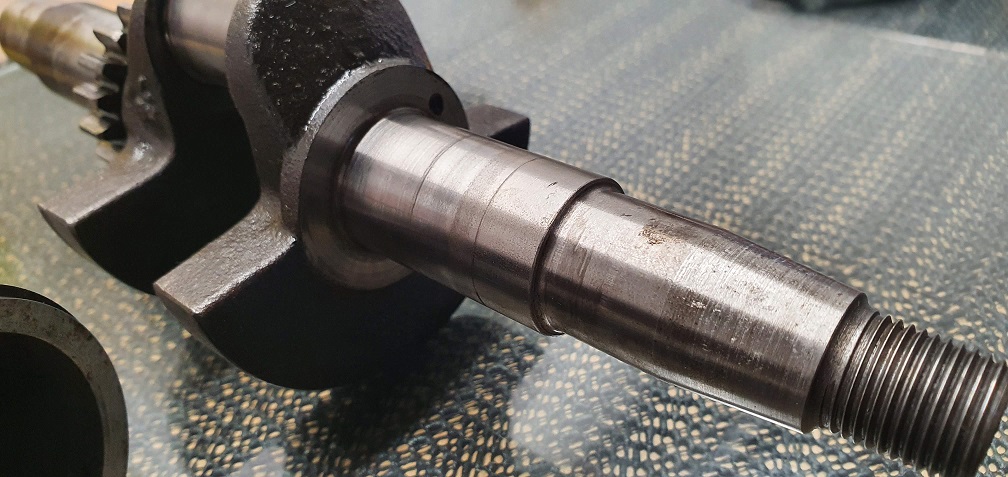
The taper faces of the crank and flywheel both nice and clean with no rust
Both crank oil seals could do with being replaced, and armed with the part number 86-8769 there seem to be a few sources online for obtaining these. It looks like BSA used the same seals on some Bantam models too which helps. Villiersparts list 86-8769 seal with dimensions of 1.43" x 0.93" x 0.20" however measuring the removed seals, they seem deeper at around 0.26". Inner diameter measures 0.98" but I assume a little wear has occurred over the years. 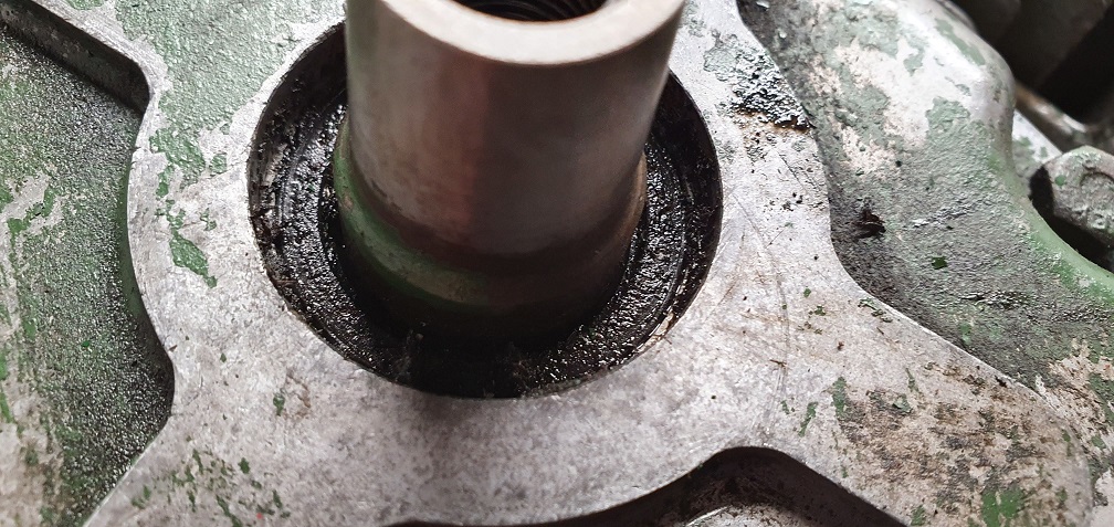
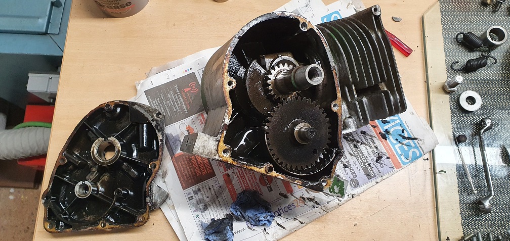
Opening the block revealed a 'carpet' of thick sludge at the bottom - it looked like some sort of material in there but no, just sludge!
The spring mounted gear trough - to keep a supply of oil for the camshaft sprocket teeth to pick up and fling around the engine when running? Why the spring mount?
does this weight act as a
does this weight act as a sort of governor system to limit how high the F12 engine can rev?
Not so much a rev limiter as an energy store. The rev limiter is your throttle thumb. Like many machines of that era the Marquis is quite a quick machine and being ungoverned has to be driven with a finely balanced throttle. Warm up the engine, engage the traction clutch, then carefully open the throttle to engage the centrifugal clutch. From there on that flywheel will take care of small load variations. With practice you will mow the lawn on the throttle, only using the clutch lever for emergencies and while emptying the box.
Oil seals. Can’t remember when I last changed a seal. Unless they were wet I would leave them alone having made sure that the crankcase breather was in good order and working correctly. However you appear to have a wet one on the pto side so perhaps changing both is a good idea. As far as I know BSA/Villiers used standard seals so they shouldn’t be an issue.
Oil trough spring. No idea, just a neat way of doing it?
I see, thanks for the
I see, thanks for the explanation. I'm looking forward to eventually starting my marquis driving lessons once this all goes back together :)
While the parts are soaking to loosen up some of the gunk, I've had the points and condenser off to inspect and clean up the points as they look pretty dirty and a little pitted. The HT lead is squashed/melted in one spot so I'd like to replace it if possible - does the end of the HT lead screw down into the coil housing (like on my Suffolk coil), or is this lead part of the coil moulding and therefore can't be removed/replaced? The parts list does show S0935 as HT lead so hopefully it is just a case of needing unscrewed from the taper headed screw in the hole

HT lead - unscrews as per the
HT lead - unscrews as per the Suffolk. Looks like the little felt lubrication pad is missing from between the two little forks. If I’m not converting to electronic I just put a light smear of heavy grease on the cam.
Good spot :) Although it was
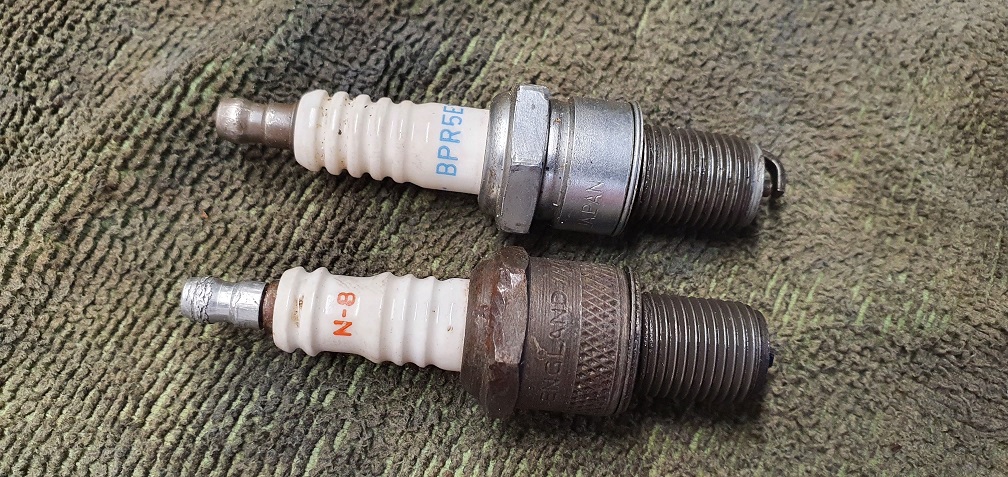
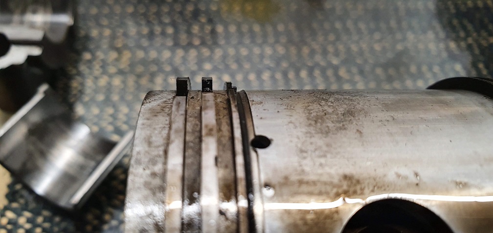
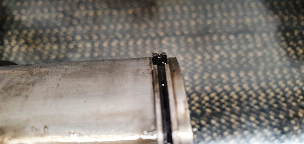
Good spot :) Although it was actually present before I removed the stator plate, but it was in a sorry state - so I will be replacing it with a spare new one that I received in the pack with the new points I ordered for the suffolk. Thanks for confirming about the HT lead - I'll get that removed and finish cleaning the points up today. Piston, rings and conrod coming out and checked for wear according to the figures in the book. Conrod bolt lock washers are available but will see if i need piston rings first before ordering for reassembly. I'll pick up a couple of spark plugs too - this engine has an original Champion N8 which has probably been in there for some time and due for a replacement, and the other engine has an NGK BPR5ES. The Champion N8, as per the book spec, is equivalent to an NGK B6ES looking it up online, although I've read on here that the B5ES is possibly more suitable? One other thing I've noticed on this engine, compared with the other sloper I have, is that the piston doesn't reach the very top of the cylinder at TDC. It falls short by around 0.040" nearest the valves, and around 0.090"
The other sloper engine has the piston crown flush with the top of the cylinder at TDC. Would this indicate possible wear on the crank journal/bearings, or is this normal on an earlier engine? When checking the timing I'll need to add this on when measuring from the block face as I only have vernier calipers and no dial gauge. There are score marks to indicate the timing but I'll double check it to make sure.
Te R on a BPR5ES plug denotes
Te R on a BPR5ES plug denotes a resistor type as used on a car, so unsuitable, TV sets no longer get their pictures broken up by HT sparks due to the ultra high frequencies. So not needed now. Is it the pic slightly out of focus, or does the exhaust valve face in the casting needing a grind in? Every little helps, I thought that one valve was 'stepped' but it seems now to have been simply carbon. Enjoying the rebuild.
Te R on a BPR5ES plug denotes
Te R on a BPR5ES plug denotes a resistor type as used on a car, so unsuitable,
Being a resistor type plug does not make it unsuitable for a Sloper but a resistor plug should not be combined with a suppressed plug cap - either or, but not both. Having said either or, I’ve recently read that Villiers recommend an unsuppressed cap and a resistor plug as the preferred choice.
The P in an NGK description denotes an extended nose / insulator plug type, which in some applications can cause a problem but doesn’t appear to in a Sloper. The original Champion N8 had a standard nose. The 5 or 6 in the NGK number denotes the heat range, the 5 being the hotter, so may be a better choice for an engine with oily tendencies but they tend to be equally happy on either.
For the difference in piston height to be down to big end or crank wear would signify that something fairly catastrophic amiss, but further investigation will reveal all - or not. One advantage of getting an engine to run, however badly , before strip down is to ascertain whether it’s a smoker or has any nasty knocks.
Thanks both for the
Thanks both for the information on the plugs and types. So it looks like the BPR5ES on the newer engine that I have is actually ok, as that one doesn't use a suppressed cap and just has a brass spade connector with a hole in it. That plug looks fairly new so I can leave that one and just get a BP5ES for the older engine which uses a suppressed connector cap
When I check the gap, should the spark plug gap still be as per the original N8 plug, and in the book, of 0.030" when using the newer equivalent plugs?
Valve chest covers certainly have some high and low points, so using various grades of paper on my glass plate I managed to flatten the mating surfaces out
Initial few passes highlighted the high spots
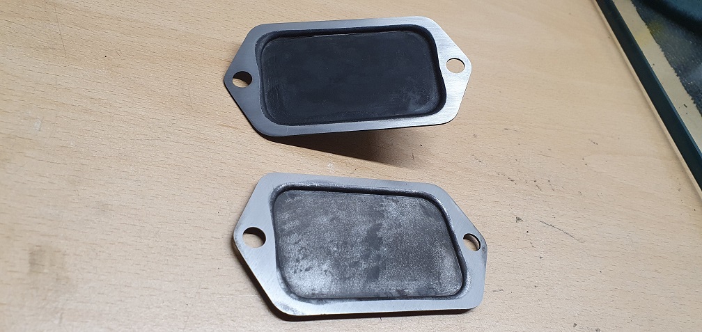
Cover with fuel line support from the newer engine, and the plain cover from the older engine
Te R on a BPR5ES plug denotes
Te R on a BPR5ES plug denotes a resistor type as used on a car, so unsuitable, TV sets no longer get their pictures broken up by HT sparks due to the ultra high frequencies. So not needed now. Is it the pic slightly out of focus, or does the exhaust valve face in the casting needing a grind in? Every little helps, I thought that one valve was 'stepped' but it seems now to have been simply carbon. Enjoying the rebuild
I haven't had a proper close up inspection of the exhaust valve seat in the block as yet - it may need a grind as it could be a bit of corrosion or it may just be stubborn carbon. The intake seat is certainly in good condition. I don't have any means to grind valve seats sadly but hopefully it won't need that. Enjoying the rebuild so far and learning more with each step :)
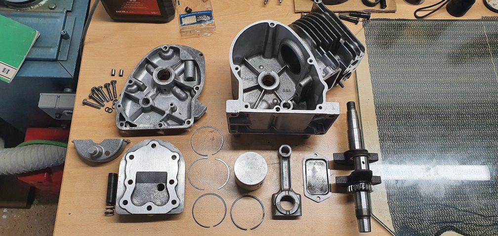
The engine is now completely
The engine is now completely disassembled. The crank looks in good condition with no damage/scoring that I can see, however the inner surfaces of the con rod big end bearing shells show some discolouration in the centre - they feel completely smooth to the touch however I don't know if this is heat discolouration or lack of lubrication/too think an oil film at some point so would appreciate some advice
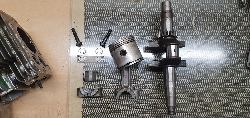
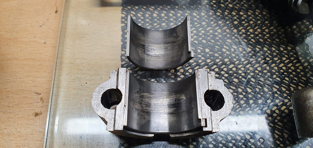
The cylinder looks ok other than a bit glazed
I'll measure the rings and the gaps to check the level of wear but I imagine the rings may need to be replaced
I think that depending on the
I think that depending on the ultimate use of the machine you can probably get away with just cleaning everything up and running a flap wheel up and down the bore. Anything more may be determined by what parts are available. A quick look at L&S Engineers site shows very little for an F12, not even a set of standard rings. A check with Meetens and Villiers Parts May be worth while.
Well I'm hoping that the
Well I'm hoping that the mower, or at least one of the two that I am restoring will be a fully working machine which will happily mow the lawn for years to come. The mk4a I did witness running and cutting well, however the mk4 (the current engine being restored) had no spark initially. I'll be very happy if I can get them both restored to full working condition.
I did note the lack of F12 parts on L&S - however looking up the part number on my big end bearing shells, 86-2552M, I see that this does come up on L&S (without the M), but listed for the F15 engine. I also saw the conrod lock washers, 87-1565, are also shared between both the F12 and F15. Having never seen a F15 engine I don't know how similar it is to the F12, however they certainly seem to share a few of the same parts from what I can see. Hopefully this will make it easier to obtain the necessary parts. Standard size big end bearing shells are available, however I'm not sure quite how bad any surface corrosion would be as they do state with their parts that they can show signs of age. The replacement flywheel I obtained from them was in great condition, just some light tarnishing on the magnet faces which cleaned up fine.
I will see if I can lay my hands on a micrometer to check the crankshaft journal is still within spec, 0.9990/0.9995" and if so, hopefully I can just replace the bearing shells with standard sized items.
As careful as I was, the middle ring did snap when removing it, perhaps quite brittle given the age, but this one is identical in spec to the top compression ring, so I can measure the ring and bore wear with that one. I will use my honing tool that I used previously on the suffolk to just lightly break the glaze on the bore providing it isn't massively out of spec.
The F15 is a very different
The F15 is a very different configuration cast iron block lump but if the part numbers are the same for those components you are in luck and safe. L&S stuff may be a bit dirty and “stores soiled” but is usually fit for purpose. The only issue I’ve had was with some “ new, old stock” condensers that looked ok but electrically were not good, but they were credited without question.
Shame about the broken ring but accidents happen. A useful dodge for removing or refitting rings is to use three strips of 3/8” wide shim ( I use some old feeler gauges) . Slip one behind one end of the rig and work it around lifting the ring from the groove , then insert the next one, and so on until the three are in position and then slide the ring up an off . The process can be reversed for refitting. Sounds a bit Heath Robinson but it works and is “ a universal size” , whereas any ring expander gizmo never seems to be quite right.
When I first started messing about with engines in the late 50s quite a lot of ring sets did not come ready gapped and the appropriate amount of metal had to be carefully filed off. In those days it was not unknown to fit a +10 ring set into a worn standard bore having gapped them to suit.
Thanks for the piston ring
Thanks for the piston ring removal/fitting tip - a very simple idea and will certainly help to hopefully avoid any further mishaps! Sounds like the F15 is quite a bit different, in fact, I've looked it up and found a restoration video online which shows the F15 engine if anyone is interested - https://www.youtube.com/watch?v=lpDowU9eYi0
Trying to measure the piston rings, after digging out my feeler gauges. The rings are so far measuring fine according to the book specs for width and radial width, however the diameter readings don't seem to be even close to the book. Should the ring diameter be measure with the ring removed and decompressed, and measured from outer edge to outer edge, or are they measured from inner to inner edge? Regardless which measurement I take, they don't tally with the book. I would expect slightly smaller diameter readings due to wear, and that would generate a larger ring gap when fitted in the bore, but the readings I'm getting are a bit larger than what's in the book, so must be measuring them wrong.
Are the upper 2 rings on the piston compression rings, the middle is a 'scraper' ring and and oil control ring is fitted just above the skirt?
Also when watching that F15
Also when watching that F15 video, I noticed the Piston doesn't come all the way up to the top of the bore at TDC, the same as on my engine, so perhaps this was the case on 'early' engines....
Somewhere amongst your
Somewhere amongst your concerns about ring sizes you lost me but my official Villiers publication gives the following dimensions.
Nominal bore size 2.234/325”
Piston rings, all, 2.323/2.324”
Closed new ring gap, .006/.0011
Bore wear is checked at right angles to the gudgeon pin and should be measured at three places swept by the rings and shouldn’t exceed .0010” No mention is given for ovality.
The end gap for used rings inserted into an unworn ( unswept) area of the bore and squared up using the inverted piston should not exceed .0020”.
I would suggest that those are all the figures that are needed for an in service overhaul as against a full engine recondition.
The book shows a 4 ring piston. Two compression rings, a stepped scraper ring and a plain scraper ring which looks like what is more often referred to as an oil control ring fitted just above the skirt. However I can’t remember any engine that I’ve worked on in the last 20 odd years having more than three rings and no spare lower groove.
Crankshaft thrust washers. You will have noticed that these are grooved on one side. It will be interesting to know how you found the orientation of the grooves. I’ve found them either way round and sometimes one and one.. The book in front of me now shows them with the grooves outwards. As the crank and cam gears are straight cut and not exerting any sideways force as if skew cut I don’t suppose it is too important - but......
I'm not surprised I lost you
I'm not surprised I lost you - I lost myself reading my own post back! It made sense in my head at the time of writing at least......
Thanks very much for the book specs - there are a couple of figures there that don't appear in my maintenance manual, so that helps.
So I've cleaned everything up and started measurements again, and things make more sense to me now. Here is a pic showing the piston and the 4 rings. That's interesting to hear you haven't come across a piston with 4 rings in all that time.
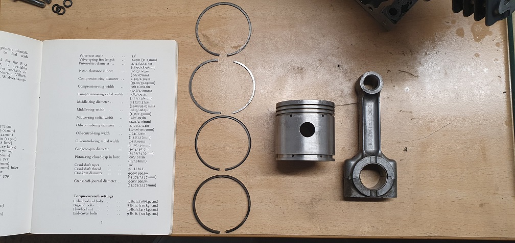
I've never seen one with a ring above the skirt, but I don't have much practical experience to go on, only pictures I've seen over the years!
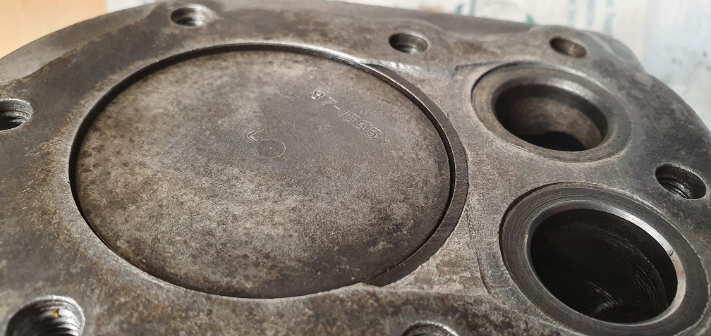
The parts list shows a part number of 87-1638 for the piston, however my piston shows an engraved number of 87-1555 and a letter 'L'
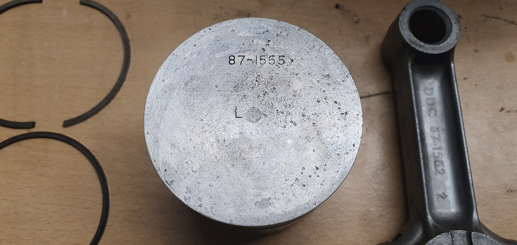
Likewise the parts list for the conrod shows 87-1561 where my rod has 87-1562.
Without a bore dial gauge I can only try to measure for bore wear by using one of the rings and checking the change in end gap at 3 different levels up and down the swept area, and doing this at 3 different points around the bore circumference. This should at least give an idea of how much change there is in bore diameter between the original unswept area and the swept area.
From what I have measured, it seems there isn't actually a huge amount of bore wear, as the ring gap only changes by around .0004" /.0005" at most, so well within the .0010" wear limit. I'm obviously aware this isn't the most accurate of readings but should suffice.
In terms of the rings themselves, when measured in the unswept area near the bottom, the end gaps on all but the skirt ring are approx .024" so a bit out of the .020" spec allowed for used rings. With the broken second compression ring, I need to get a new set anyway so will see about getting hold of a set of standard sized rings.
Crankshaft Thrust washers - I did spot them in the parts diagram and also saw a post about it on here - I think it was Chris' marquis restoration thread - however they were nowhere to be seen on this engine! I've double checked in case they were stuck to something that I removed, or had somehow fallen into the sludge but no, they don't seem to exist inside this particular sloper engine. The plot thickens.......
The plot thickens.......
The plot thickens.......
Indeed it does; intriguing.
All the differences would seem to add up to an earlier version of the engine than that shown in either your or my parts books.
Assuming that the engine has not been re-bored - no plus sign on the piston - measuring the ring gaps of a new standard ring set will give an indication of the wear. However you can purchase a set of relatively inexpensive telescopic bore gauges that can be used in conjunction with your digital vernier.
It certainly is turning out
It certainly is turning out to have a few unexpected surprises/differences. I'm making enquiries about piston rings - sadly not something that is shared with the F15 engine, as that has a larger bore and piston. I'll have a look at the telescopic bore gauge options out there as I think it would be useful to have for things like the bearing shells as well.
I'm looking forward to stripping the newer sloper engine and finding the differences - including the thrust washers - I'll be sure to take some pictures as I find them for reference. For now, I've only got the space to work on one engine at a time so now that everything is apart and cleaned up I can see what I need to order ready to start the rebuild
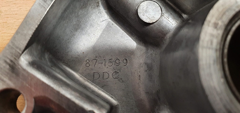
The BSA logo crankcase cover differs from the part number in the book by one digit also, showing 87-1599 rather than the expected 87-1598 - curious as to the DDC letters as also seen on several items including the head and conrod?
Put a light cross hatch pattern back on the cylinder wall, not sure if it needs a bit more...
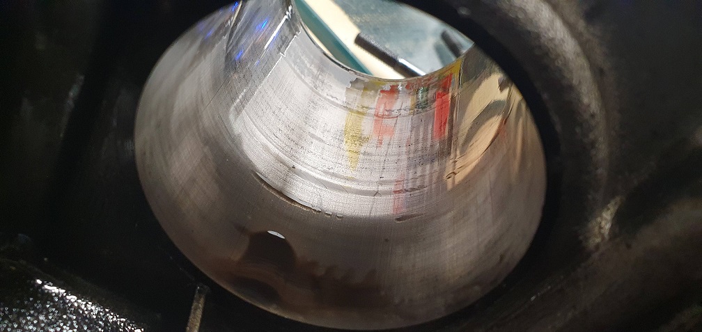
The inlet valve seat has cleaned up very nice and appears in very good condition, however the exhaust valve seat has some degree of corrosion as expected. The seat contact area seems a little wide/worn however I will give the valve a lap and see how both look afterwards
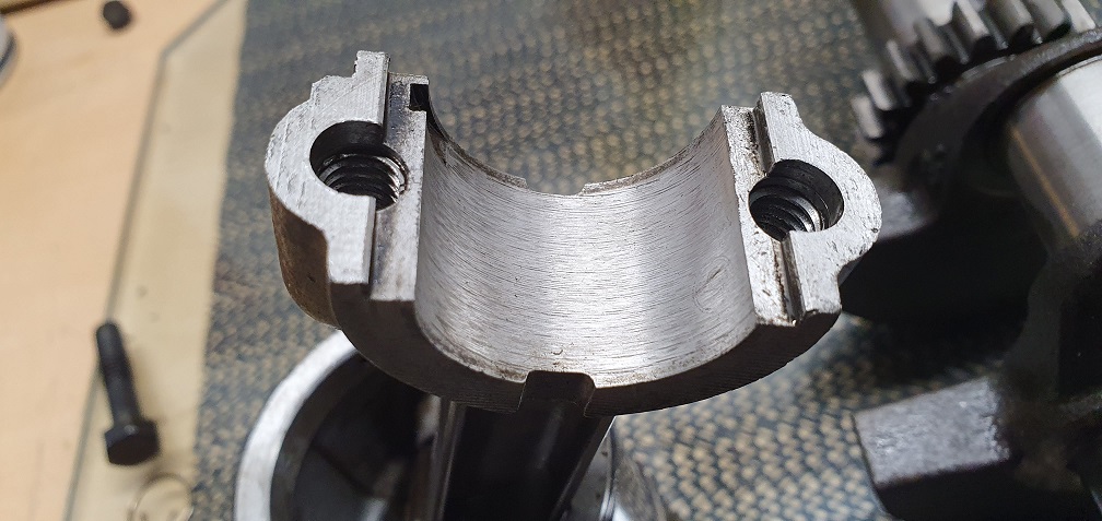
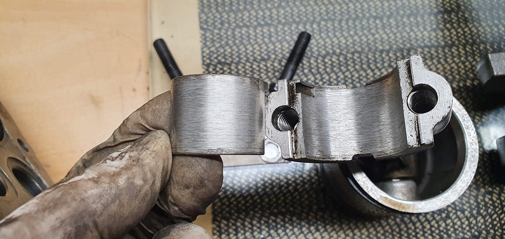
The crankcase cover bushing/bearing feels smooth and looks in good condition
However the one on the magneto/flywheel side is very badly scored
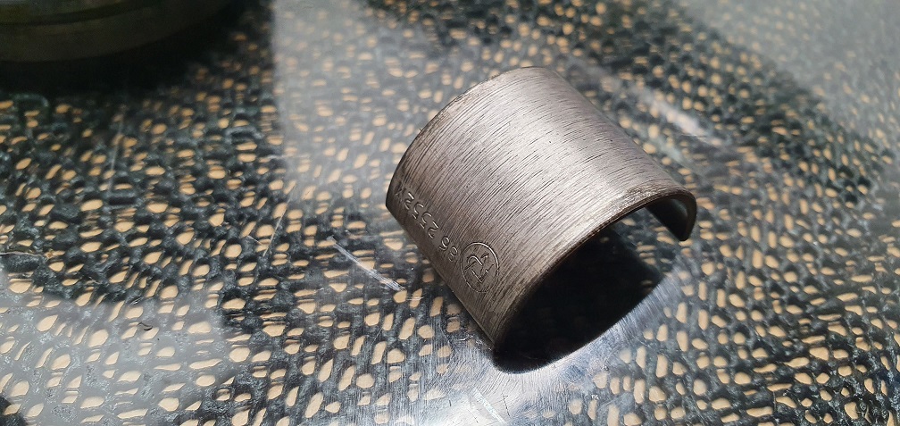
I have a feeling this bush may be tricky to source, part number in the book shows as 30164 - 'Bearing'. Nothing showing online so will make enquiries, again sadly not shared with the F15 as that one is available on L&S with part number 31902. The manual I have illustrates the sizes of the required drift for the removal of these bush/bearings, which I might be able to fabricate, just depends if the bush is available anywhere.
I'm enjoying your rebuild
I'm enjoying your rebuild thanks.
You probably haven't been looking at my Villiers engine rebuild, but I bought a pair of these bushes a couple of weeks ago for about a fiver including postage, mine are one inch o/diameter and 7/8ths inner. Length is about 3/4ers if I remember correctly.
My only problem so far is finding the new bushes are too long, ( 1 inch) so need cutting down, I ruined one in my lathe because the cutter caught one split area and it picked up badly.
 Original is in the centre.
 Another way would be to mount the bush onto a 7/8ths mandrel, but being split bushes I haven't yet decided just how to stop them still opening and/or spoiling mandrel too.
 The odd thing is finding the old bush a tighter fit onto the very thick end of mandrel than the new one! Looks like bush needs fiuling to make it smaller on one end of split area.
 Upside down I'm sorry, just couldn't see!
I did put the name of the suppliers on my other posting.
I bought my bushes from
I bought my bushes from "Bearing Boys" site, paid by card and bushes took about five days to arrive.
Perhaps they could have supplied them shorter so that I didn't need to cut mine short, but there wasn't anyone to answer my query at the time.
Good luck with your build, modern mower engines like Briggs have crank running directly in the ally cases, as do most Hondas!
Put a light cross hatch
Put a light cross hatch pattern back on the cylinder wall, not sure if it needs a bit more..
Difficult to see but the cross hatch looks to be rather a shallow angle. Aim for 45 degrees . 300/350 rpm with a fairly brisk reciprocation and plenty of lube. When done wash out and thoroughly scrub with hot soapy water , dry and wipe with solvent on a light coloured cloth. If you’ve done the washing properly there should be no “ grey” transfer to the cloth.
Bore gauges. Top, pucka BS. blue wallet, cheapish from ebay
I'm enjoying your rebuild
I'm enjoying your rebuild thanks.
You probably haven't been looking at my Villiers engine rebuild, but I bought a pair of these bushes a couple of weeks ago for about a fiver including postage, mine are one inch o/diameter and 7/8ths inner. Length is about 3/4ers if I remember correctly.
Hello DJD, glad you are enjoying the build thread. I haven't been browsing the other forum sections as much of late so haven't seen your Villiers engine rebuild thread. I will definitely check it out though. A strange coincidence that you are dealing with these same crankshaft bushes currently! Thanks for the info about the size and supplier, I will have a look at Bearing boys. I did wonder if it would be a readily available generic item rather than having to hunt for the genuine, probably obsolete part. Out of interest, does your original bush have the villiers part number printed on the back of it?
Difficult to see but the cross hatch looks to be rather a shallow angle. Aim for 45 degrees . 300/350 rpm with a fairly brisk reciprocation and plenty of lube. When done wash out and thoroughly scrub with hot soapy water , dry and wipe with solvent on a light coloured cloth. If you’ve done the washing properly there should be no “ grey” transfer to the cloth.
Thanks - the picture doesn't show the pattern all that well, but it does look a little shallower than the intended 45 degree angle, so I will give it another light hone. After all machining is done, and valve lapping, all the parts including the block will be subject so hot soapy water bath and scrubbed until nothing comes off on a clean cloth. I will do this right before reassembly starts to try and avoid any flash rusting and get some oil on the relevant surfaces as quickly as possible.
Thanks for the bore gauge examples, I'll see what I can pick up.
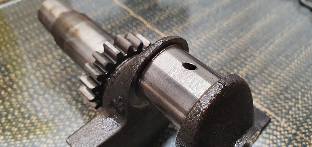
One issue I've discovered with the crankshaft is the small oil way between the big end journal and the main journal was blocked with thick tar like sludge. Took some cleaning out but got it clean as a whistle
I wonder if this could have led to the big end bearing shells having the discolouration down the middle - possibly the oil film got too hot if it couldn't drain away, or if fresh oil couldn't get through to it?
One issue I've discovered
One issue I've discovered with the crankshaft is the small oil way between the big end journal and the main journal was blocked with thick tar like sludge. Took some cleaning out but got it clean as a whistle
Definitely a good move. Back in the day we used to use pipe cleaners (as in smoking) for that sort of job.
Welcome back!
Welcome back!
I usually find F12 block faces to be fairly flat. If you have a straight edge or decent steel rule just check it out in different positions using a feeler gauge under it.
Heads, yes, they can often benefit from a rub over an abrasive sheet on a surface plate. If the stud has just been used to find some more depth of thread after an overtightening incident a useful source of a replacement bolt is the box of saved Briggs head bolts from scrapped engines. Right diameter and for all intents and purposes , thread. ( original probably Whitworth, older Briggs, UNC * which at that diameter is as near as damn it !) If, however the stud diameter has been increased due to a major snafu you will need to check out what has been used. Unless that stud really offends you I would be inclined to leave it alone.
* Side valve engines to be safe, later OHV may be metric.