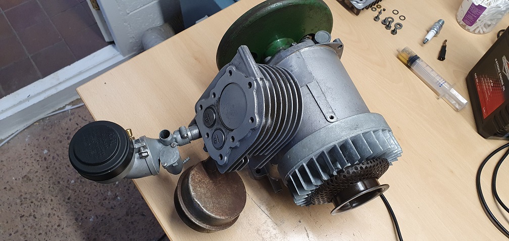
A brace of Ransomes Marquis - Restoration
The finish line was in sight for my Atco / Suffolk Super Colt and I wanted to get something lined up for my next project. I spotted a Ransomes Marquis 18" non runner due to no spark (here we go again!), and when I went to look at it, the chap also had a running Marquis which was a slightly newer model, but had a fuel leak at the carb. Needless to say I ended up getting them both in the back of the car, with assistance!, and brought them home.
I'm not going to go to the lengths I went to with the Atco - as good a learning experience as that was, I now want to keep the mowers cosmetically as they are, bar a couple of little touch ups here and there, but overhaul them mechanically to get them both running well. Hopefully I can use one of them as my regular mower as the 18" cut will hopefully make things easier around the garden, and I do like the look of these mowers.
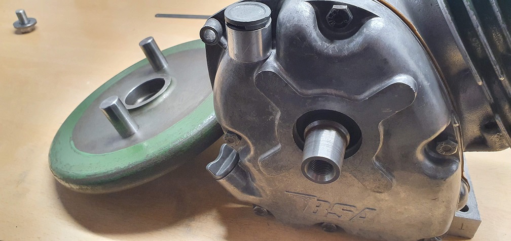
I would like to get an idea of manufacture date for both, and one should be easier as it has the plate on the side which says Mk4, but they both have the same BSA marked F12 Sloper engine
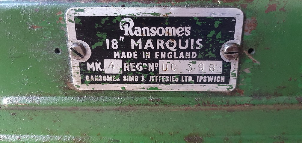
Mower 1 - Ransomes Marquis 18" Mk4 - Reg No. DC 398

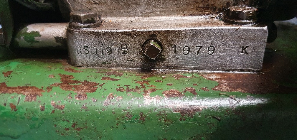
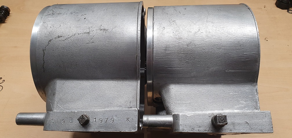
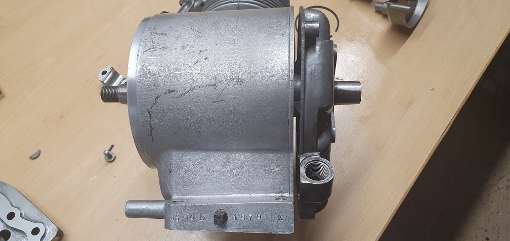
No numbers on the exhaust side of the block like the other mower, however the sump drain plug side has the following - RS 119 B 1979 K
Mower 2 - Ransomes Marquis 18" Mk??- No ID Plate

Forums
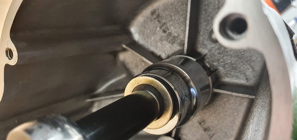
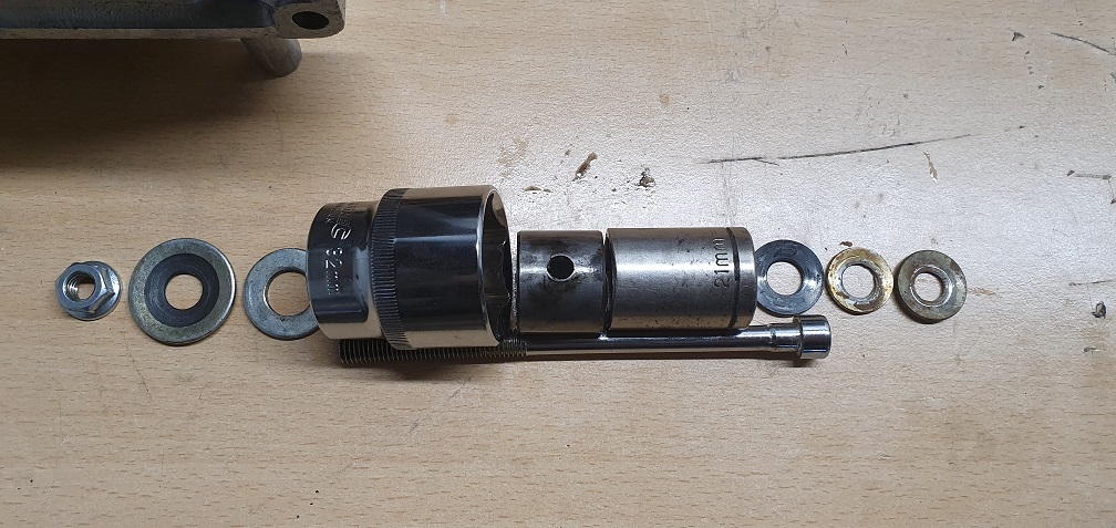
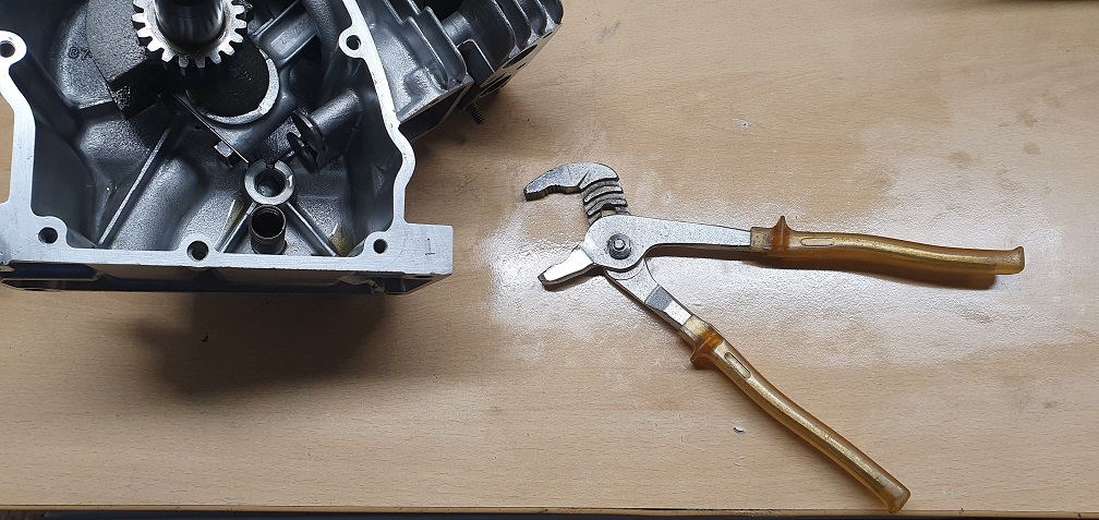
I've created a sort of puller
I've created a sort of puller as opposed to a drift as I figured it would be gentler on the housing rather than smacking a drift to try to dislodge the bush. The largest fitment on my slide hammer set was just the right size but I figured I would try that if my puller didn't work. The puller was a success - made from bits and pieces I had in the garage, namely a 21mm socket, a 32mm socket, some threaded bar with an allen head at one end, a 13mm flanged nut and some washers. The 21mm socket was just the right outer diameter to push the bush through and just clear the housing, and the 32mm socket was large enough to accommodate the bush as it was driven out. A 6mm hex bit in a screwdriver on one side, and a 13mm socket on the other and it had the desired effect. Plus it was good to dust off my metric sockets which have been very neglected for some time now!!
Out it comes
I can can measure up the exact dimensions now and see about getting a replacement.
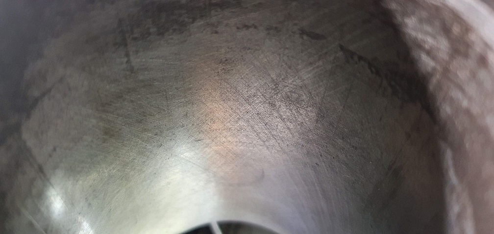
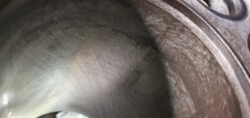
Further honing of the cylidner bore resulted in hopefully a better angle of cross hatch
and valves lapped
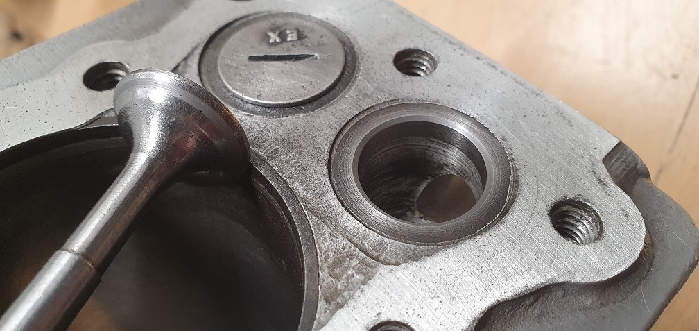
Happy with the intake, and the exhaust hasn't cleaned up too bad. In an ideal world the exhaust valve seat would do with a grind, probably with 3 angles to reduce as the valve face contact band as its a bit wide, but then the block would probably need to be reamed out to accommodate a valve guide (none fitted to this particular engine) before being able to then cut the seat accurately, due to the wear in the current 'guide' area on the exhaust side. I'll just have to see how it runs when it's all back together, but hopefully this won't prevent it from being a serviceable grass cutting machine. Maybe one day I'll treat myself to a set of Neway cutters and I can learn a new skill....
Good job you're doing. You
Good job you're doing. You might find the exhaust valve clearance has decreased or even disappeared, I use a wooden block, just a bit of planed 2 X 2 softwood, drill a hole in it centrally that makes valve a snug or tight ish fit then grind the end down with an oilstone.
The block needs drilling in an accurate pillar drill or similar, that way end of valve is ground accurately.
Thanks, just waiting on
Thanks, just waiting on piston rings arriving, but I have the new big end bearing shells and crankshaft oil seals now at least. Once assembly is underway I will check the valve clearances and set to the required .006" for both inlet and exhaust. Good pointer for the wooden block. I don't have a pillar drill or similar to make a good 90 degree hole for the valve stem. When I rebuilt my Suffolk engine (a fairly comprehensive thread on here!), I carefully offered the tip of the valve stems up to the fine bench grinder wheel several times and kept re-measuring in order to slowly remove the required amount. I will probably do the same with these, unless there is only a tiny fraction of material to remove, in which case I'll see if I can come up with a suitable wooden block and use an oilstone or similar as suggested.
The main issue remaining is trying to source a suitable split bearing bush for the crankshaft. The measurements required are 1.000" Internal Diameter, 1.125" external diameter and 0.910" length, with a 1/4" oil hole half way along. I've searched and cannot come up with the correct replacement, so I may have to bite the bullet and get an original Villiers item. Before ordering though I'm going to try to get the other engine stripped in case that one needs either bush replaced and I need to order more than one, to at least save on postage!

Your post 103 of the main
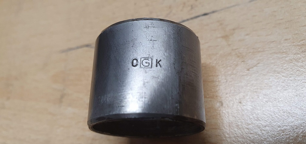
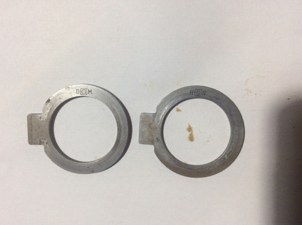
Your post 103 of the main bearing bushes with the manufacturer’s markings reminded me of seeing similar markings and sent me on a rummage into the dismantled Sloper bin to find two crankshaft thrust washers taped to their crank. They are visually and dimensionally identical other than one being marked DGM and the other HGN. Why identical washers from the same engine with different alpha characters.
I know that you found no thrust washers on your block, so presumably the crankshaft end float is set/ controlled by the thickness / number of crankcase cover gaskets. May be worth checking before you get too far into the rebuild.
SKF site is worth exploring:
SKF site is worth exploring: skf.com/uk/products/plain-bearings.
Does this site nor accept simple links to others?
Thank you, I hadn't looked on
Thank you, I hadn't looked on their site yet. The nearest I can find on there is still a bit too short and doesn't have the necessary oil hole. I've managed to get a quote for the original part number from Villiers parts, which I'm going with, to avoid having to modify an off the shelf one to suit. I will remove the crankshaft form the second engine to check if that one needs either bushing replaced before ordering.
Your post 103 of the main bearing bushes with the manufacturer’s markings reminded me of seeing similar markings and sent me on a rummage into the dismantled Sloper bin to find two crankshaft thrust washers taped to their crank. They are visually and dimensionally identical other than one being marked DGM and the other HGN. Why identical washers from the same engine with different alpha characters.
I know that you found no thrust washers on your block, so presumably the crankshaft end float is set/ controlled by the thickness / number of crankcase cover gaskets. May be worth checking before you get too far into the rebuild
That's interesting about the manufacturer markings. It seems the middle letter G is constant and encased in a square with differing flanking letters. I wonder who the manufacturer actually was for these parts - presumably the G refers to their name?
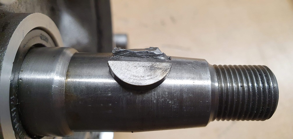
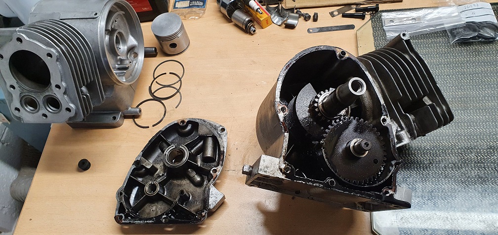
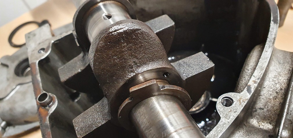
I've had to strip the other engine to check the bushings before placing my order, so I have now uncovered my first sloper thrust washer. I've taken pictures exactly how I found it for orientation reference. A completely stuck flywheel key would not budge and showed signs of attempted removal in the past. After soaking overnight in penetrating spray and trying a couple of unsuccessful removal methods, and with limited further options, I had to drill it out using a 2.5mm HSS drill which was slightly narrower than the key. I used the key from the other engine as a depth gauge and marked the drill so as not to go any deeper than the depth of the key
Getting there
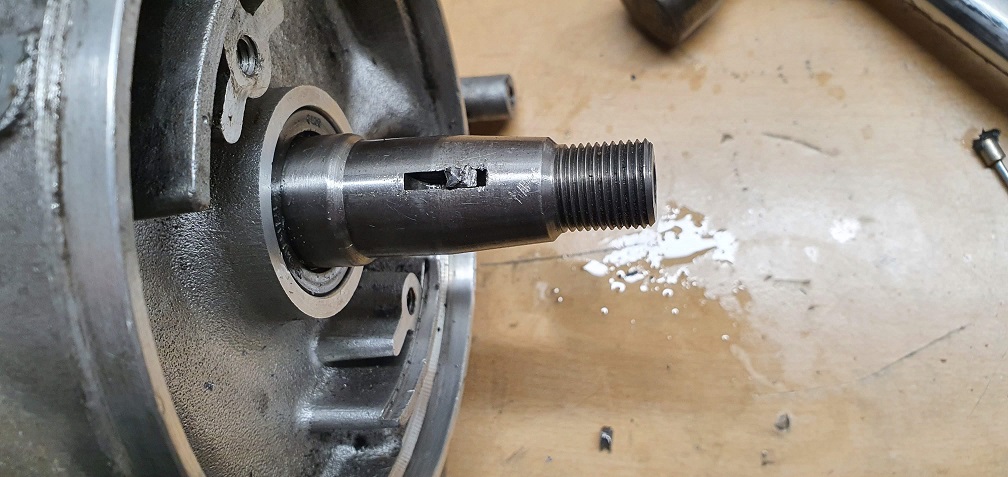
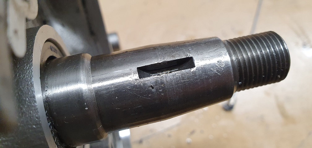
and out at last, with no unintended damage :) There may be other better ways that I could have tried If I had more tools/equipment such as some sort of gas torch to try heating and cooling the key etc. This done the job however, and allowed me to proceed with the crank removal to check the bushings
Another weeping oil seal - good job I ordered a set of 4!
Thrust washer
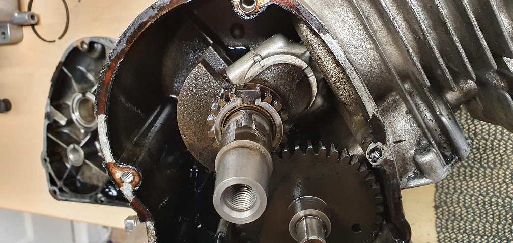
With the same manufacturer markings, the letters JGP on this one (picture also showing cam timing marks)
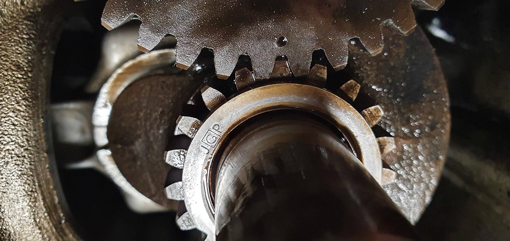
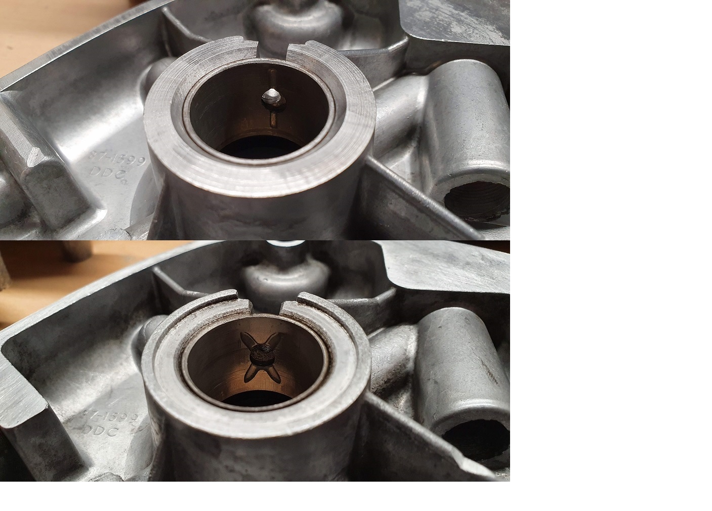
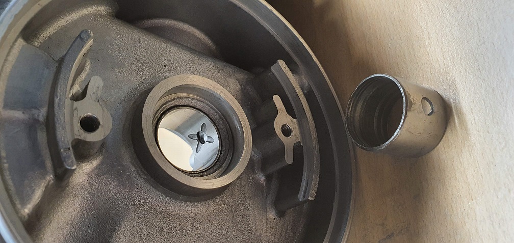
I assume the cutout at the top is where the thrust washer is located when re-assembling (like above?) The crankshaft bush in this crankcase cover is in good condition - and appears to be a slightly different design with an 'X' where the oil hole is. This crankcase cover is different to the older one I have, and has a different part number of 87-1599 presumably modified to use these thrust washers.
Certainly looks as though you
Certainly looks as though you had a battle royal with that key. I’ve never had a flywheel key put up a fight but in other similar situations I have found that supporting the offending shaft and positioning a small parallel punch about a third of the way along the key and striking it sharply will rotate the key out of its keyway.
Unfortunately neither Google nor Safari have been any help with the source of the bushings and thrust washers. I wonder whether the Villiers Parts items are New Old Stock Villiers items or whether they have commissioned them from a current manufacturer.
That flywheel key certainly
That flywheel key certainly was stuck in there, no rust anywhere to be seen, just as if it had been repeatedly hammered into place at some point in it's life. Thankfully cheap and easy to replace.
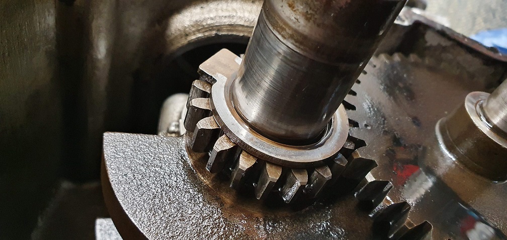
I uncovered the second thrust washer fitted to the other side of the crankshaft - again the grooves were facing inwards, towards the rotating shaft
which seems to cover the oilway from the main crank journal?
Curious as to the composite make up of these thrust washers - the grooved side appearing copper like?
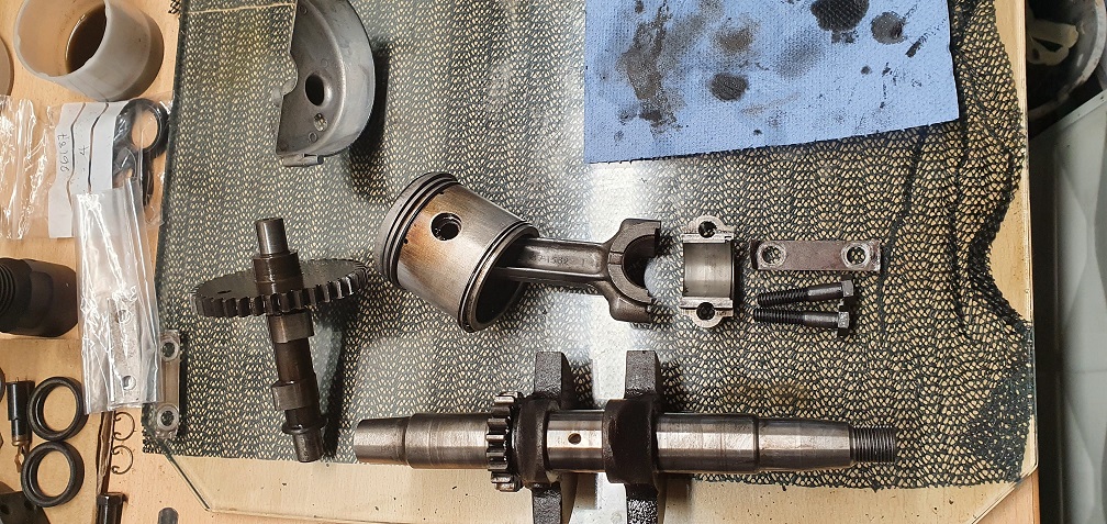
Big end bearing shells and crank all look fine on this one, as do both bushings, so just the one new one needed for the other engine
Interesting colouration of the piston walls on each side of the gudgeon pin
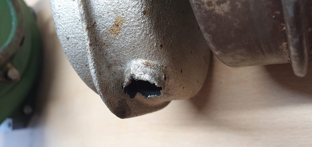
I wanted to tackle the stuck 1/4" UNC exhaust fixing bolt that sheared off when I tried to undo it
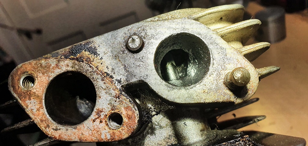
I filed the end flat and used a centre punch to create a dent for a drill. I figured I could use the same bolt extractor set that I used to successfully remove the stuck oil drain plug on the other engine...
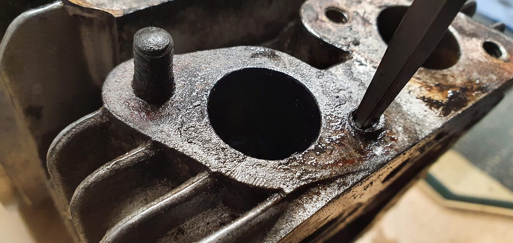
So I drilled a hole down into the centre of the stuck bolt and hammered in the extractor. Tried working it gently back and forth as I had been soaking the area for a few days with penetrating fluid. Sadly, the extractor was not up to the task :(
Brilliant, so now I have a stuck bolt AND the end of the extractor stuck in the middle of it!!
SO what are my options here - I'm not seeing anything that I can tackle myself... I don't think it will be possible to drill out what's there with a larger hole and then tap a new larger thread, due to the proximity of the head bolt thread that runs down through the block not far from this existing hole
Wondering if I need to find a local engineering company that can either use a pillar drill and larger size drill bit to drill out what's there, or potentially weld a short stud in place like the existing stud? Unless there is space to drill deep enough and thread in a short stud to match the other fitting?
Don't like defeat but I'm out of ideas for a solution that I can try myself....
I hate those so called screw
I hate those so called screw extractors, the broken bolt is usually loose enough that drilling a hole down the centre and driving anything into it will remove it, or it is a bolt screwed down to the bottom of a blind hole and nothing will move it. If your 'screw extractor' is as hard as the ones I have seen, then it will probably be extremely difficult to drill it out. You probably need to find someone with a spark erosion machine.
Nightmare scenario , a
Nightmare scenario , a sheared hard steel extractor. I don’t like a tapered extractor of any variety as they tend to expand the stud/bolt and tighten it against the block. The way forward would have been to lay a U of mig wire on the block then a large washer welded to the stud and then a nut to the washer. The U is to stop the washer being pulled tight onto the block; the shallow hole of the washer is far easier to weld through than starting trying to weld down through the nut and then the nut on its side can be welded to the washer. If you look back to my Anzani restoration you will see that every bottom blade screw had to be given that treatment.
As I see it there are two options. 1 find an engineering shop or tool makers with a spark eroder. 2 . Again an engineering shop with a mill or heavy duty radial drill that can take a stubby centre drill without being deflected and drill it out - depends on how hard the stud is.
EDIT. Sorry , I was typing while H was replying!
Thank you both for the advice
Thank you both for the advice. Pretty disheartening after things were going so well, but without welding gear/tools/experience my fairly light duty tools just weren't up to the task. That Anzani restoration sounds like fun and games - I'm sure I've read it before but will go back and have another read!
Oh well live and learn and all that. I'm sure I will find a way around this as I can't let this be a showstopper for this engine. Thanks for the link Angus, I will have a good look at that site. I've not come across spark erosion before so keen to see the wizardry in action! Hopefully I can send the block off somewhere and the service won't be too costly. Not sure I can wait until this lockdown business is over so I can travel somewhere localish to get it sorted.......
It’s what is known as a bit
It’s what is known as a bit of a B****r but most experienced comes at a cost. Try searching on tool / pattern makers or a sizeable engineering engineering firm that may use a spark eroder. When I started working life with a big US earthmoving machinery manufacturer , in the middle of the factory was the “ Reclaim crib” staffed by skilled guys with all sorts of wizardry for dealing with broken taps etc.
Sorry to see your project
Sorry to see your project come to a sudden stop, getting the left overs welded to a big nut and washer is maybe first attempt, as others have said, tungsten carbide will drill out drill bits and taps if need be, but setting up your block in a milling machine is a job for a machine shop and a machinist I'd say, there are lots of good videos on YouTube where good men and tools etc. can laugh at small jobs like this. Problem is that the setting up takes longer than the drilling out. I call 'easy outs' "hard outs" myself! Never did any good with one, my old friend Bob at the golf course showed me how to use the softer tang end of a file, hammered into a hole in a broken off smaller stud working.
I have a set of left hand drill bits also that occasionally work, stud often winds out with bit.
It's frustrating but lesson
It's frustrating but lesson most definitely learned. After checking over the rest of the stripped engine, everything is in good condition - valves, valve seats, valve stems, crank etc so it's definitely worth saving - I just hope it doesn't cost an arm and a leg to put right. I've send an email off to a dozen or so EDM companies asking about spark erosion and an approx cost, and included some pictures. I'm getting some interesting responses so far, from down right rude, telling me I'm a d***head for using an extractor, to others saying I'm looking at a cost of at least £150 upwards for the removal. Sadly nowhere local to me comes up in any searches so I'm looking at postage costs of probably £15 or so to cover both ways when sending the block off. A costly mistake....
There are a couple of sellers
There are a couple of sellers on that auction site that regularly offer most of the innards of F12s but they never seem to sell offer the crankcases .On the assumption that they see more value in the parts rather than the whole engine and possibly weigh in the cases as “ clean or dirty ally” it may be worth your while to contact them. However as you have discovered there are “ early and late” designs when it comes to thrust washers etc so questions would need to be asked.
Assuming that you come to the conclusion that spark erosion is not a viable proposition I would be tempted to go back to what perhaps should have been your original course of action - welding to the stud. Find some one who is an experienced welder - not just a man who says he can - and see if he will give it a go. Difficult see just how recessed your stud is but under the circumstances, I would give it a go.
I will make some further
I will make some further enquiries with some local companies regarding welding, and also keep an eye out / make contact with any sellers of F12 parts on that site too. I suppose welding a short piece of stud to match the existing stud on the opposite side would be out of the question, as the weld around the base would be in the way and prevent the gasket from sitting flat against the block? The remains are flush/just below the surface of the block, so nothing protruding to weld onto as such. There isn't even 1/4" of extractor in there, so I wondered if a small drill could be used to sort of chase out around the outside of the extractor part enough to at least get the extractor out. Or run the engine with no silencer..... :)
An experienced welder may
An experienced welder may well be able to fish the bit of extractor out. In which case you could be back into accurately drilling out the remains of the stud. I would perhaps make a guide or jig bolted to the remaining inlet and exhaust mountings to keep a drill bit centred . Jig sounds a bit grand but a piece of flat mild steel strip with accurately marked and positioned holes is all that is needed. Start with, say, an eight inch hole above the sheared stud and enlarge both the jig and stud drilling’s at the same time.
That way you would keep everything concentric , where as by attempting to drill around the outside of the broken extractor you could end up with an oval hole , or worse, a broken drill bit.
EDIT. I posted your situation on another forum and received a suggestion of a carbide burr in a Dremel, applied with a steady hand, was something that I’d not thought about. Apparently it got him out of trouble in a similar situation.
I bought a Hayter 56 at a
I bought a Hayter 56 at a local recycle and was so glad to get it for £15 that I didn't even look underneath, why would I? It was almost starting up. About a week or two later many reasons for it being chucked out surfaced, once I'd removed the engine and pressure washed it all, every single hardened steel screw into the hard alloy deck was solid, heat and Rustola etc made hardly any difference, one inch long screw holding a flat strip bracket that fixed a front wheel on took 55 old nuts of many different sizes and threads welded on then left to cool and a ratchet used to undo the remaining threads.
I simply refused to give in or be beaten, two afternoons later I finally managed to withdraw it, turning amperage up too high at one point had melted the ally into the studs threads.
Hopefully you had a decent
Hopefully you had a decent working machine after all that with the Hayter? We have a 56 in the family which has been a solid workhorse for many years and still going strong!
An experienced welder may well be able to fish the bit of extractor out. In which case you could be back into accurately drilling out the remains of the stud. I would perhaps make a guide or jig bolted to the remaining inlet and exhaust mountings to keep a drill bit centred . Jig sounds a bit grand but a piece of flat mild steel strip with accurately marked and positioned holes is all that is needed. Start with, say, an eight inch hole above the sheared stud and enlarge both the jig and stud drilling’s at the same time.
That way you would keep everything concentric , where as by attempting to drill around the outside of the broken extractor you could end up with an oval hole , or worse, a broken drill bit.
EDIT. I posted your situation on another forum and received a suggestion of a carbide burr in a Dremel, applied with a steady hand, was something that I’d not thought about. Apparently it got him out of trouble in a similar situation.
Thanks for all the details and passing on the suggestion of a carbide burr + Dremel. I've wanted to get hold of a Dremel for some time due to their many uses, but haven't ever got around to actually purchasing, but it's on the wish list - possibly the 12v cordless one for ease of use and manoeuvrability. I Imagine one would be handy with a small brass wire wheel disk for cleaning the caked on carbon from inside the intake and exhaust ports, and area under the valve seats, although I am managing to get most of it out with some elbow grease.
I've had a quote back for around £50 for sparking it out, leaving a hole which will just require a thread tap, presumably whatever the next size up is from the current 1/4" UNC thread. If i don't have any joy with local companies and the welding option at least I have this as a backup, and probably not much different to paying a good welder to have a go and potentially take up quite a bit of time. Not cheap, but these blocks don't seem overly easy to come by so I would hate to see an otherwise good condition block go to scrap.
In the meantime I will crack on with cleaning up the block, piston, check ring gaps and fit new rings if required. As soon as I have the new crank bush for the other engine I can start rebuilding that one. Any parts that are different between the two, such as the crankcase cover to accommodate the thrust washers, I will take a picture of and upload as reference for others as I think it will be helpful for those stripping down and sourcing replacement parts like I have done.
I wouldn't be in too much of
I wouldn't be in too much of a hurry to go up a size as a 1/4:20 unc thread insert uses a 17/64th (7mm?) drill size. So even if you are left with a slightly sloppy hole a 1/4" insert should grip ok and leave all your head sizes standard .
Sort of, I had to weld up
Sort of, I had to weld up several cracks in the deck and extension at rear, chute etc. problem now is engine, ohv type, worn bore and con. rod picked up on crank etc.....
Any parts that are different
Any parts that are different between the two, such as the crankcase cover to accommodate the thrust washers, I will take a picture of and upload as reference for others as I think it will be helpful for those stripping down and sourcing replacement parts like I have done.
A real find would be a parts book for a pre valve guide and thrust washer F12. Perhaps Clive and HD Trust can search their archives ?
That would certainly be
That would certainly be interesting to see, if anyone is able to locate/uncover said parts book.
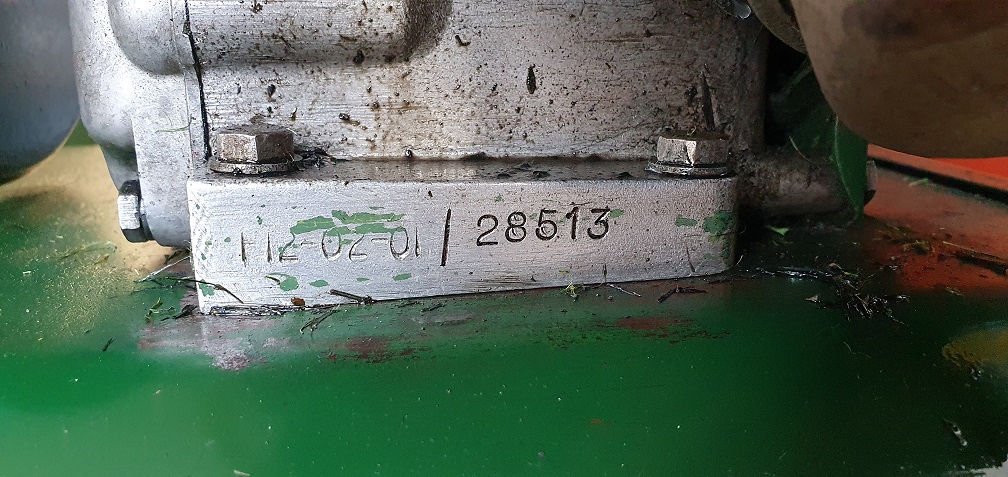
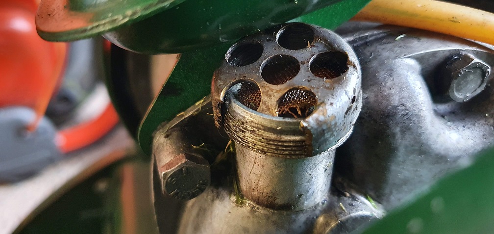
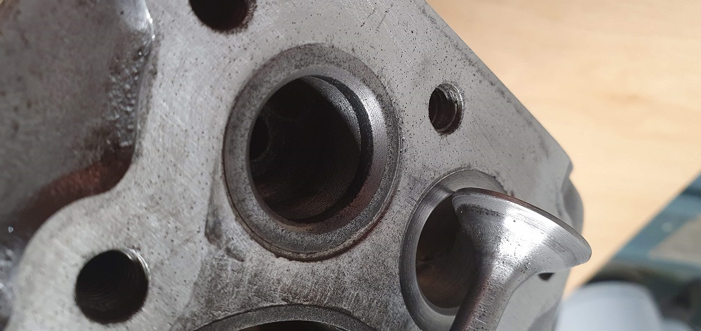
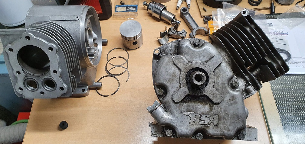
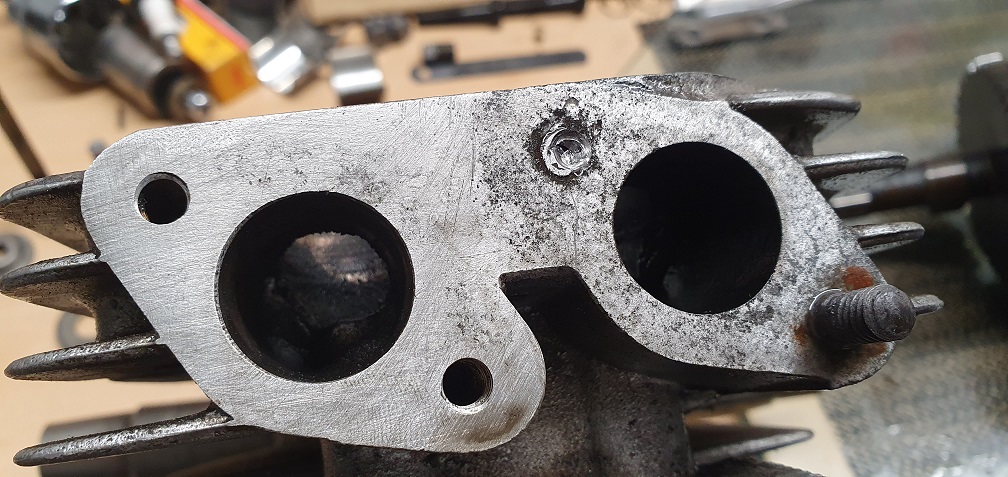
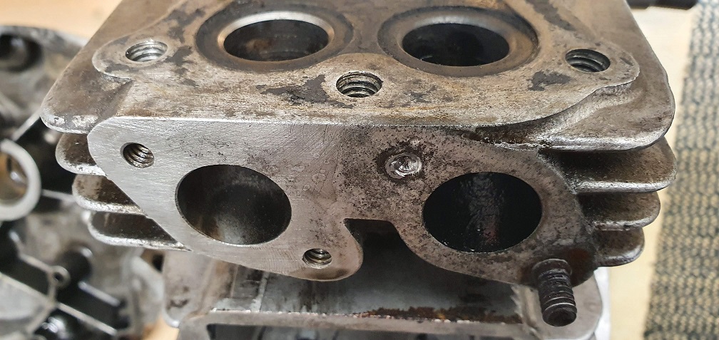
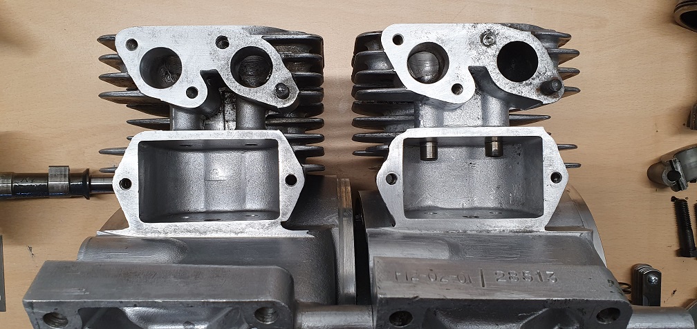
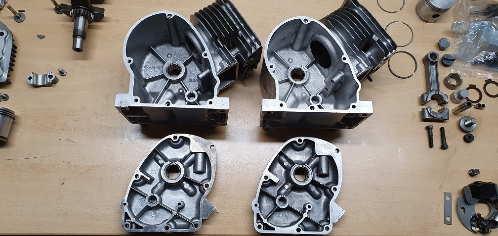
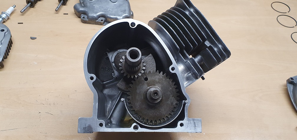
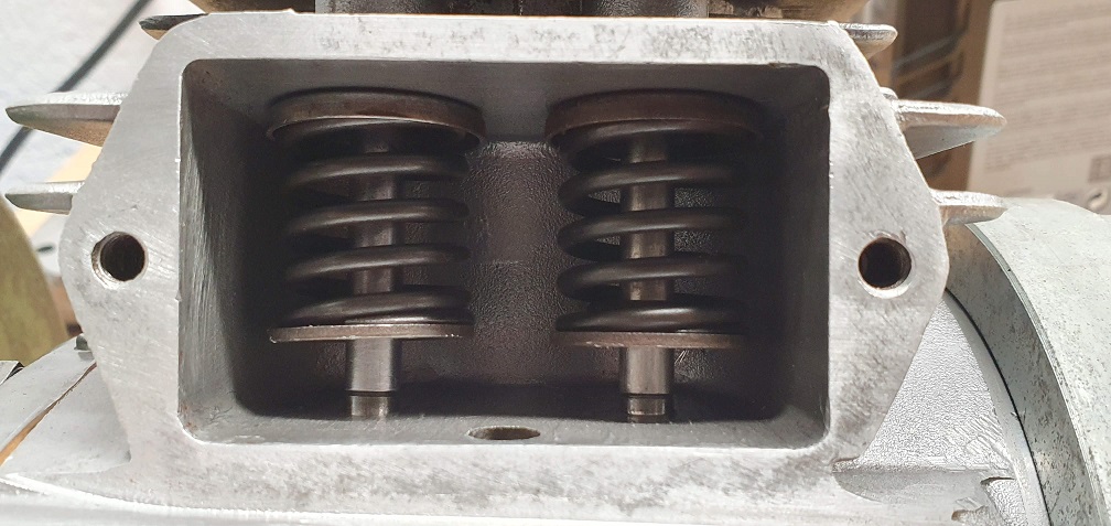
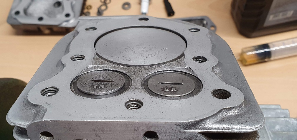
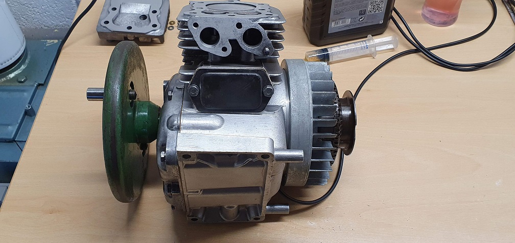
Here's a picture comparing both engines - showing the difference between the older block with no valve guides, and the newer one. The newer one with the valve guides has solid alloy between the 2 guide outer columns, whereas the older block is hollow there. Also the newer block has the F12 serial number at the bottom and the older one has the older RS119B style serial on the opposite side
As already mentioned, but to
As already mentioned, but to keep the comparisons all together, the Oil drain plug is also different - the older block uses a 1/8" BSPT plug and the newer block uses a larger 1/4" BSPT plug
Just out of interest, I know
Just out of interest, I know that the newer block and its cover will be machined internally to take the tab of the thrust washers but as far as the fit between cover and block goes, are they interchangeable? Probably just the perspective of the image but the newer block looks slightly smaller .
I had the car out of the garage yesterday which gave me access to some low down "graveyard" shelves and found a stripped out block that is machined for thrust washers but has BSA cast into it internally - no matching cover though!
Ah yes that's just the
Ah yes that's just the perspective of the photo - they are identical in size. The thrust washer and the non-thrust washer crank covers are completely interchangeable and have the same hole positions. Both of the covers that I have show the same part number 87-1599 DDC and both have the BSA logo on the outside
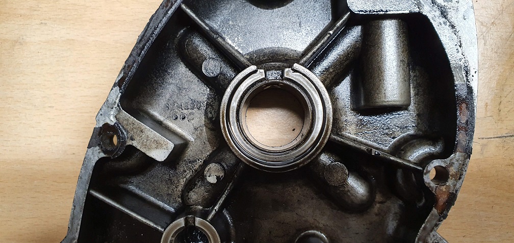
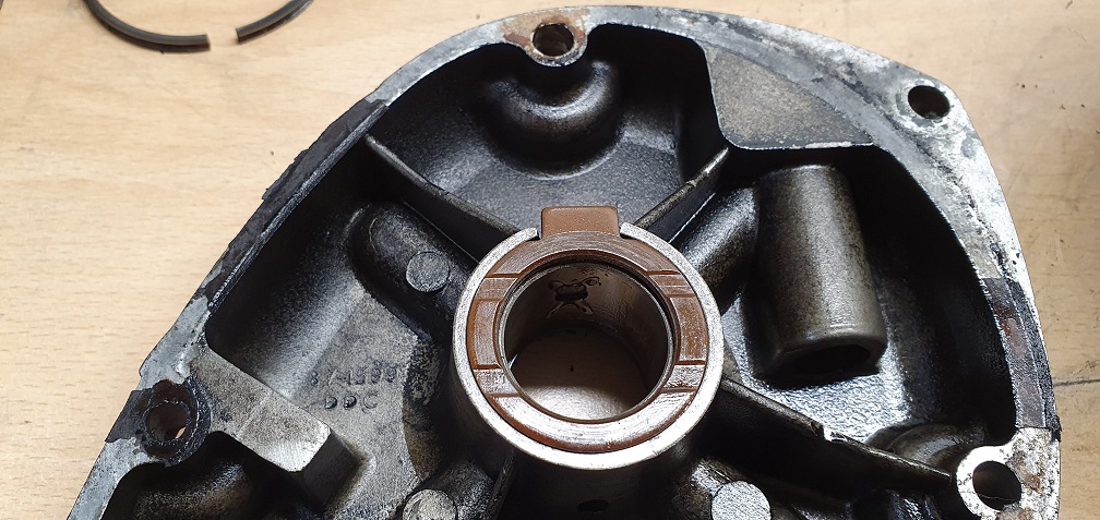
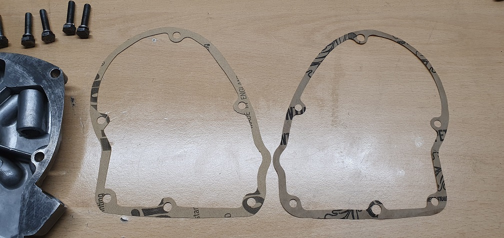
Left is the older non-thrust washer cover
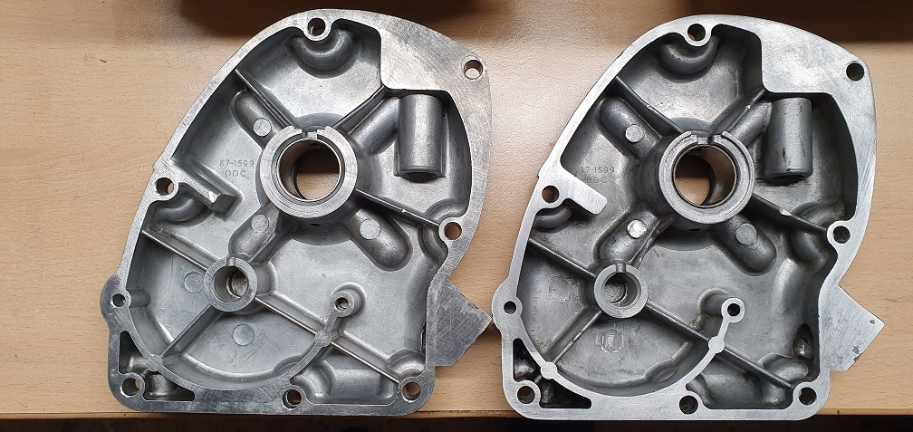
Top is the older non-thrust washer cover. On the newer cover you can see where the thrust washer tab locates at the top of the recess
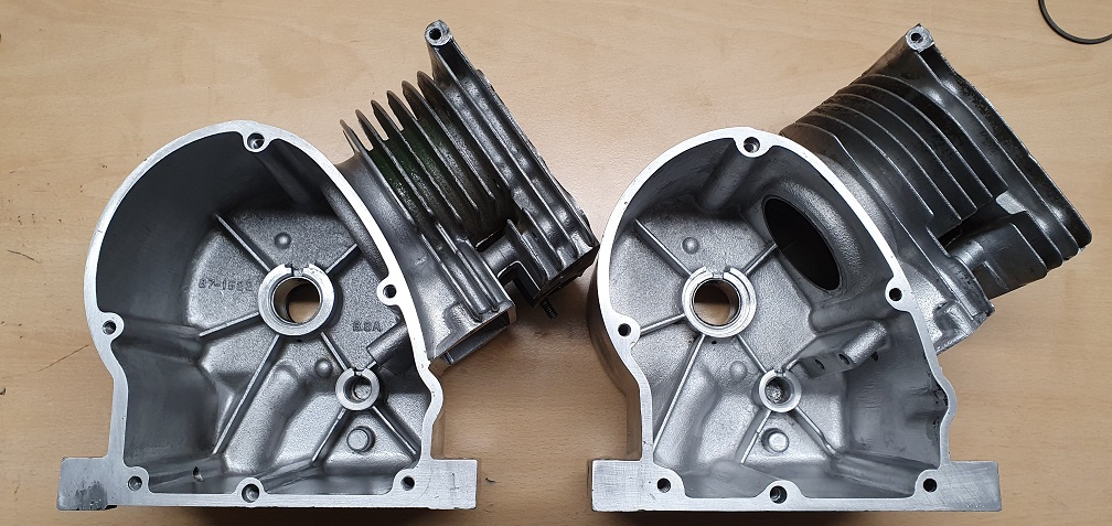
Older engine left, newer on right
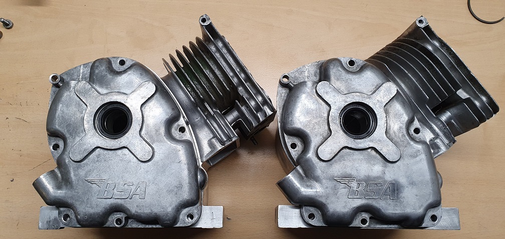
The older block has the B.S.A engraving on the inside as well as the part number 87-1522 - no markings or part numbers on the inside of the newer block (on the right)
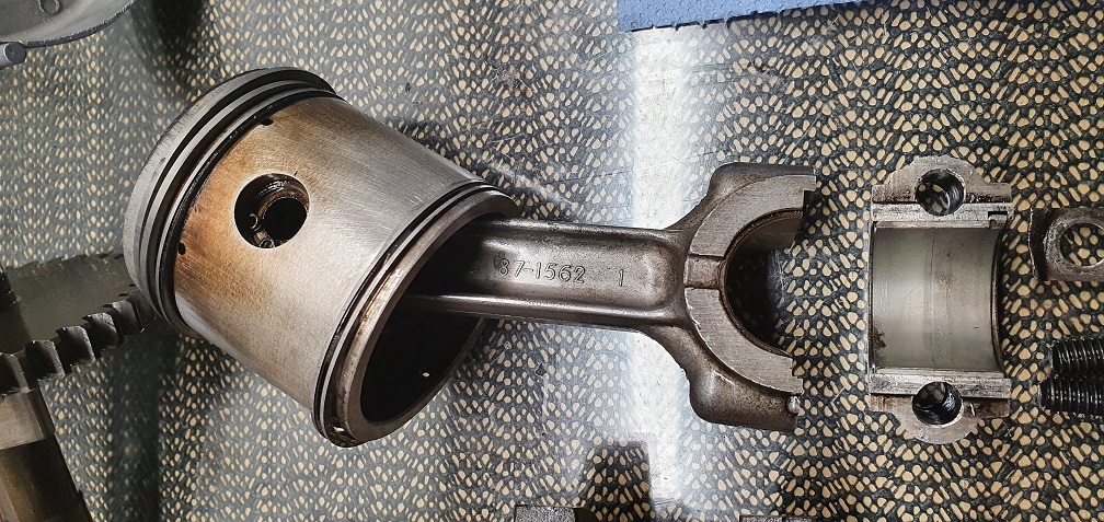
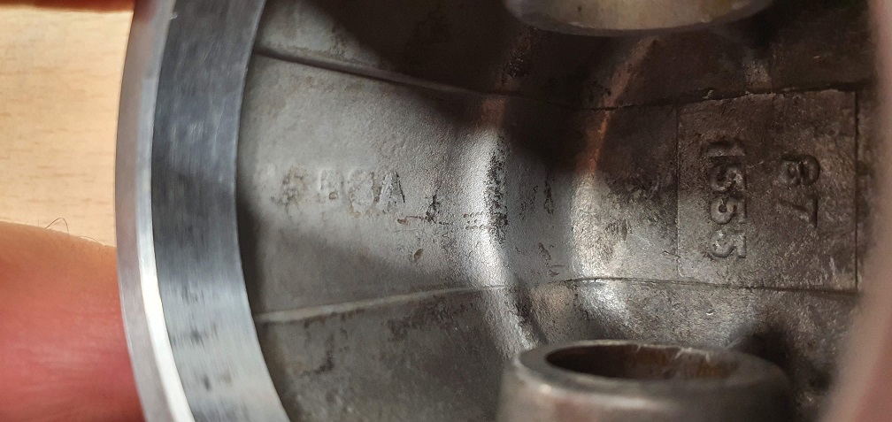
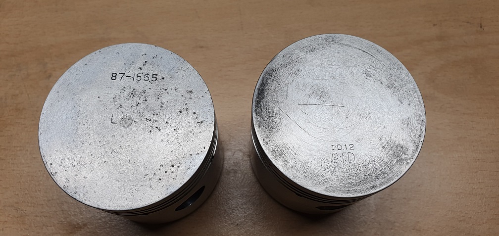
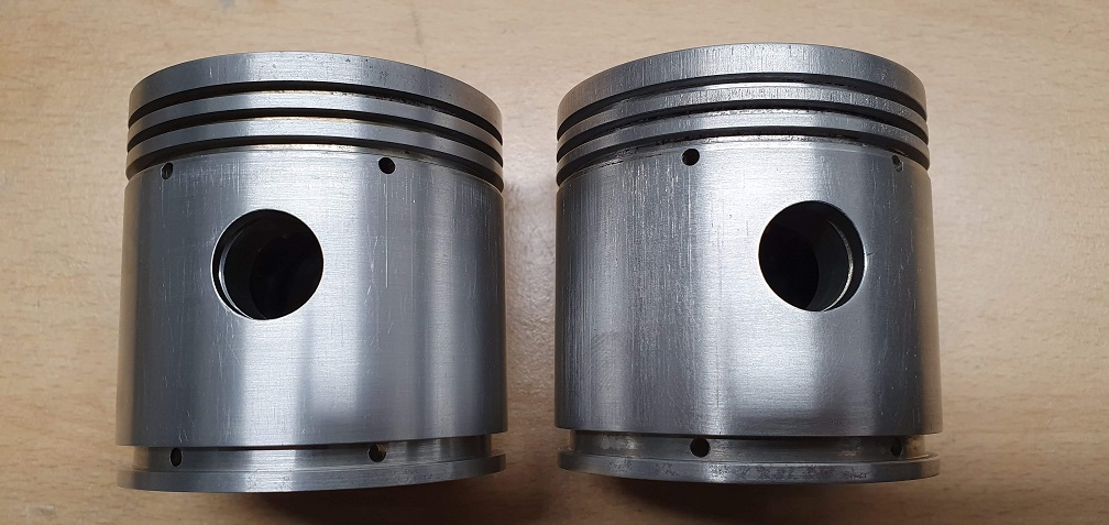
The pistons are both different in terms of manufacturer and markings. The older engine has the BSA logo on the inside wall of the piston as well as the part number 87-1555
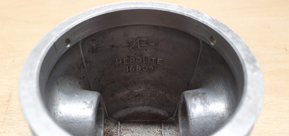
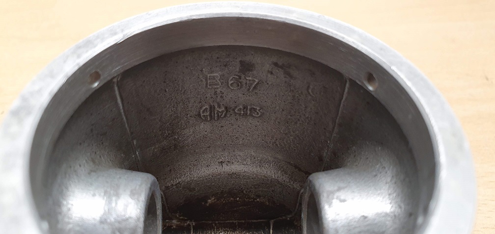
The newer engine piston is made by Hepolite with a part number 16809 and letters AE, as well as B67 and AM413
The older piston has the 87-1555 and letter L on the crown and the newer piston shows STD (assuming STanDard size) and ID.12 - and someone else's scratch marks from a past carbon removal perhaps!
4 x new crank oil seals will be fitted, part number 86-8769 - same oil seals used on some BSA Bantam bikes!
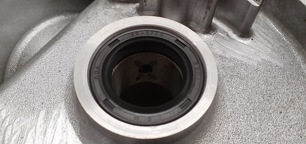
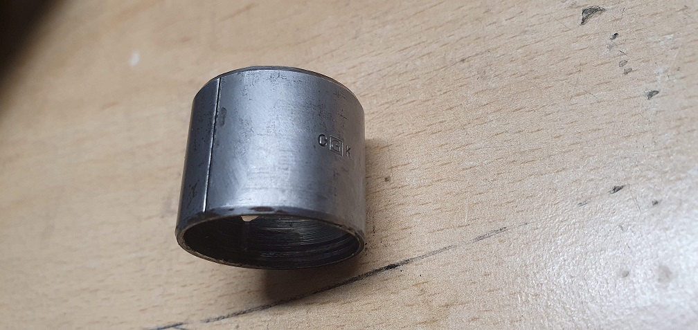
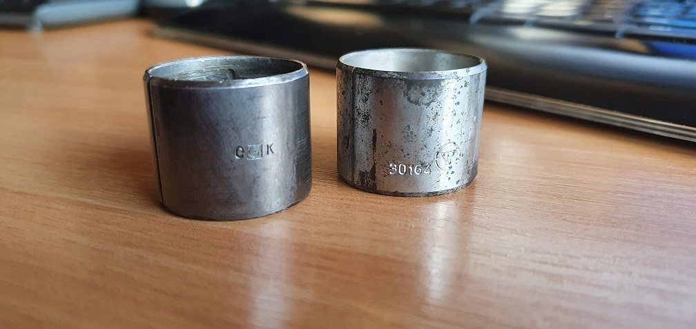
I received my new crankshaft split bush bearing, part number 30164 to replace the worn CGK marked item
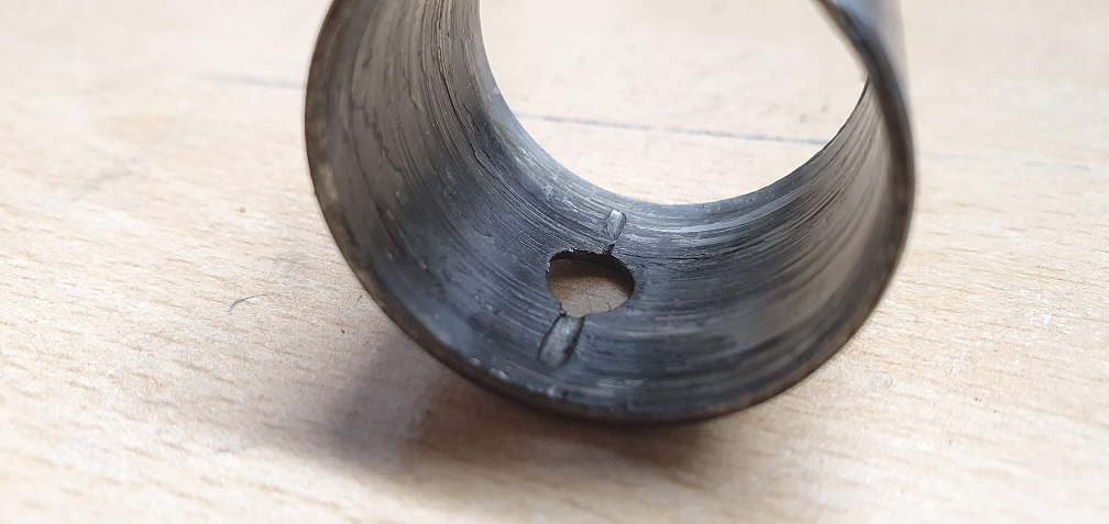
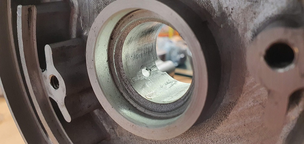
After some gentle tapping to get it square and only just started into the housing, I then used the puller I constructed to push it into place, ensuring the oil hole lined up with the one in the housing
New bearing fitted
This means the rebuild of the older engine can now begin!
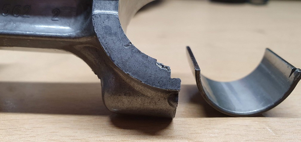
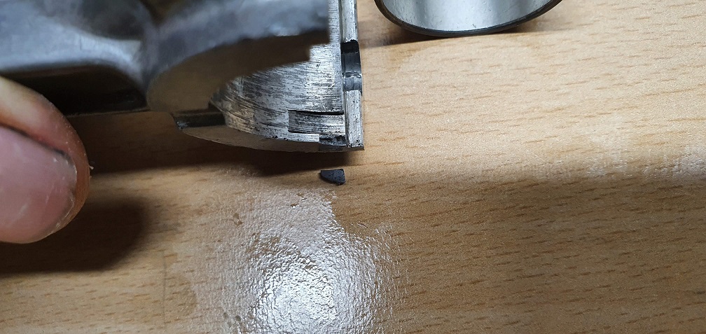
One slight issue, which I am hoping is a non-issue, is that when fitting the new conrod bearing shells, GENTLY pushing the rod shell half into place, a tiny corner fragment of the groove where the locating tang sits came away. This must have been a weakness in the casting as it took no effort to fit the bearing shell and this fragment simply came away as I did. The bearing itself is fine, and can still locate in the locating groove on the rod half ok, so I am hoping this will still be alright? Do these locating tangs help to prevent any lateral movement of the bearing shell? If so then although one side of this tang has the inner wall of the locating groove to sit against, around half of the outer wall of the groove is no longer there.
Or is it a case these grooves and tangs are simply to assist in initial fitment of the bearing shell, and the crush pressure when the cap side is torqued up, plus the sides of the main journal on the crank prevent any movement of the shells?

Just a thought, have you
Just a thought, have you tried a dry reassembly of the non-thrust washer crank into its block but using the thrust washers from the other engine? If it goes together without the end case being jacked away from the block it might suggest that its a "missing thrust washer engine" as opposed to a "non" engine ?? We need the elusive parts book!
Good thinking, I just gave
Good thinking, I just gave that suggestion a try but the end cover would not fit against the body with the thrust washers fitted in that engine - the cover sat proud by around the distance of 2 thrust washers :)
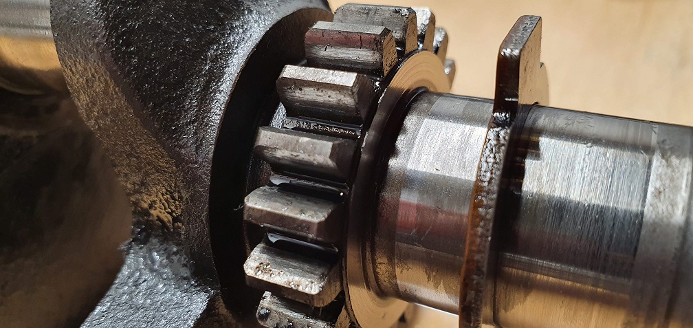
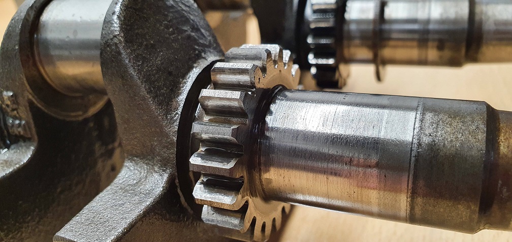
Both crankshafts are near enough identical, and share the same part number of 87-1531, however there is one slight difference - the crankshaft that uses the thrust washers has a slightly raised step on the outside face of the camshaft pinion
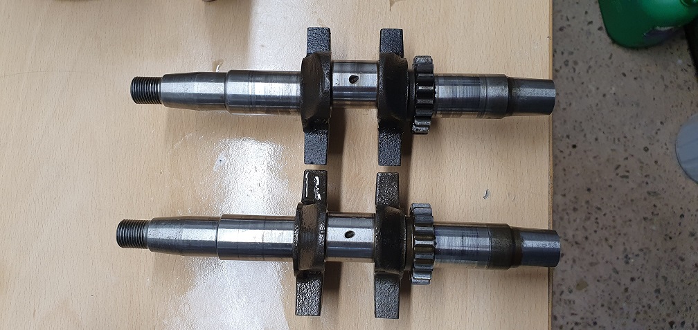
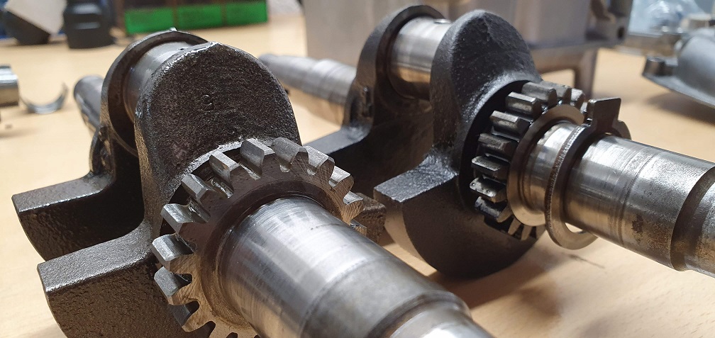
Thrust washer crank
Non-Thrust washer crank
Oh well, worth a shop, but
Oh well, worth a shot, but now we know. Going back to your query about the big end shell location, I think that the main purpose of the notch and raise bit is to stop the shells spinning within the big end with the crank. Lateral location is achieved by the machined inner faces of the crank pin.
With the correct crank in the correct crankcase ,gasket and cover, what amount of end play is there?
Thanks, I believe the con rod
Thanks, I believe the con rod will be fine as is, with the tiny corner of the cutaway missing. I've tried assembling everything and all seems good - the bearing shell still locates in the notched out bit of the rod end fine and stays there.
I will try and get some sort of number for end float. I remember comparing the two engines before strip down. The newer engine had much more of a 'clunk' when pushing the crank fore and aft, whereas the older engine had a smaller degree of movement, more of a 'click'. Very technical I know. I will fit one new gasket to this older engine and torque up the bolts and check. Without a dial gauge, I will place the end of the crank up against something solid and while holding the case, pull the shaft away, and then use feeler gauges to get an idea of end float. I have varying thickness gasket paper that I can use If I need to use more than one to obtain a suitable level of end float - using the new gasket as a template.
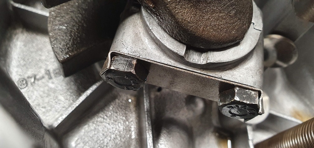
Just before I do, once I've torqued up the con rod bolts, is there a trick to getting neat 'folds' on the ends of the new con rod bolt lock washer? I remember there was more access to the whole washer on the Suffolk engine I done as the the sump could be removed, however access to the furthest side of this washer is a little limited here (bolts are only finger tight so far in the picture hence the gap between the halves)

For the lock tabs I usually
For the lock tabs I usually use a pair of sliding jaw pipe pliers. One jaw over the bolt head and one engaging the tab, squeeze and the job is done.
End float on the F12. No mention in the F12 workshop manual - or in any other Villiers manual in my possession . This combined with the fact that the F12 gasket set contains only one thickness of cover gasket would suggest that Villiers did not consider it an issue.
Thanks for the pointer. I
Thanks for the pointer. I found some suitable pliers and put some insulation tape around the jaws to try and avoid marking the bolt heads too much - seemed to achieve the required result
I refitted the cover without a gasket just to check what sort of end float there is, and torqued the bolts up to the required 9 ft-lbs. It takes quite a bit of force to get the crank to move fore and aft. Likewise I can't turn the crankshaft by hand by much at all - things feel a bit 'tight'? Not sure if this is due to so many new parts, the oil seals, the big end bearing shells. I did notice even just pushing the piston down into place with the new rings was quite stiff, so is this likely all this is? If I put the flywheel bolt in the end of the crank and use a ring spanner, I can turn the crankshaft ok, but it certainly doesn't spin over easily like it did before strip down.... perhaps things settle and loosen up a bit after things get moving. I used plenty of oil on all moving parts during assembly.
Quite to be expected with all
Quite to be expected with all the new parts that you’ve fitted . I would perhaps have possibly popped the crank in , fitted the cover but left the con rod disconnected ; just to see that all was well . In some applications new bushes would be slightly under size and then line reamed to finished size and precise alignment bush to bush. Quite to be expected that the new rings should exert a bit of drag.
Back in the day ( the 1960s!!) we would set up gear box and diff preloads with string wound round the shaft connected to a spring balance to measure the preload against spec and increase/decrease accordingly.
1960's, a little before my
1960's, a little before my time - I wonder if the same technique is still used on certain machines of that era, or any other machines for that matter - if more modern techniques can't be used for whatever reason? As long as the required result is achieved!
Before fitting the piston and rod, I did fit the crank to check fitment with the new split bush bearing - it was snug but felt very smooth. When the crankshaft oil seal was fitted and the same was carried out, that's when the rotation started to feel a bit stiffer. I can see the oil seals making good contact with the shaft (they were lightly oiled as per the book), so combined with the other new oil seal, regardless of the new piston rings, it would be fairly stiff anyway. The rod and big end bearing cap were dry fitted to the crank before hand and rotation was nice and smooth with no play, so I think things are fine and will bed in nicely once she comes to life.
In terms of end float, although a little stiff to test, there is, what seems to me, a fair amount. Measuring the new gasket, it's extremely flimsy at only .005" so it won't have much bearing on the end figure.
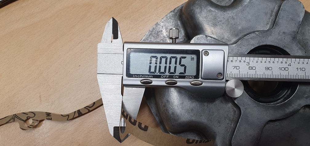
Without it in place, the end float seems to measure around the same thickness of the valve chest cover material (as a reference), around .044"
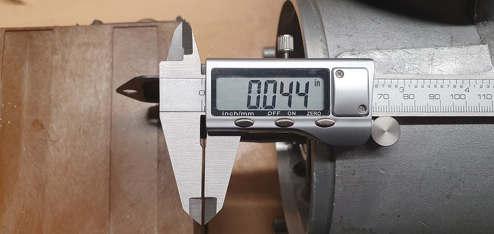
I have nothing to compare to, until the second engine is rebuilt, so I don't know if this is average for this type of crankshaft setup, or if it's excessive. From what I understand after reading up a bit about it, it's better to have a little too much than not enough? There's no way that I can see to decrease it so I'll certainly just fit the one single new gasket and continue the rebuild.
Well I appear to have reduced
Well I appear to have reduced the end float successfully to a much more suitable level. How? By fitting the correct crankcase cover. Brain fart/senior moment/take your pick. That's why I should have only done one engine at a time instead of stripping and comparing them! :) Oh well, made me chuckle after the initial shame wore off.
So in terms of end float, well it's practically non existent (with the correct cover on!). The shaft barely moves at all now. I'm tempted to use a thicker paper gasket in there to try to at least get a little bit of movement, just a few thou. I'll copy the outline and test with one of the thicker A4 gasket paper sheets I have and see if that provides enough and if not perhaps fit 2 gaskets and report back...
I created a new gasket from
I created a new gasket from some thicker gasket paper - took a couple of attempts to get it right, due to the new gasket being so flimsy, making it hard to trace around. I used the engine case as the template instead and managed to get an accurate gasket made up and punching out the holes etc. After applying the correct torque to the cover bolts, I have have an end float figure of approx .010" which feels better.
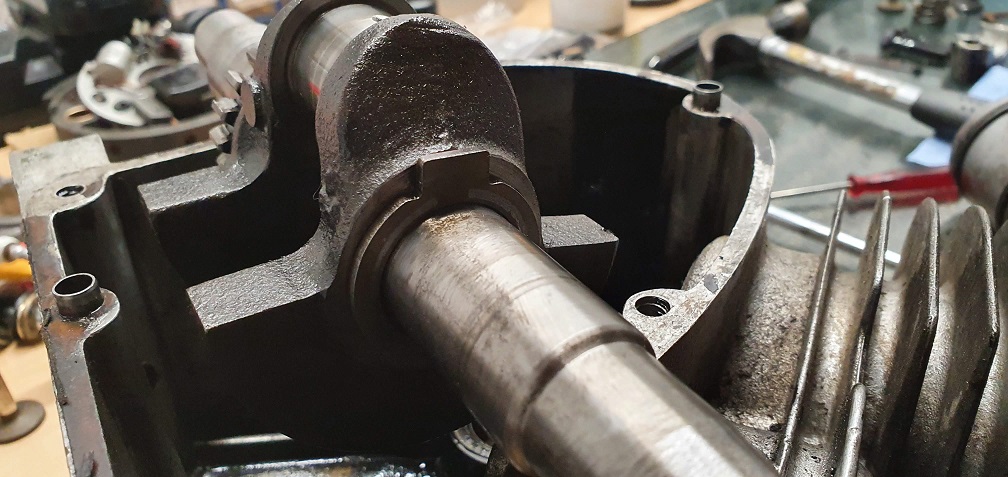
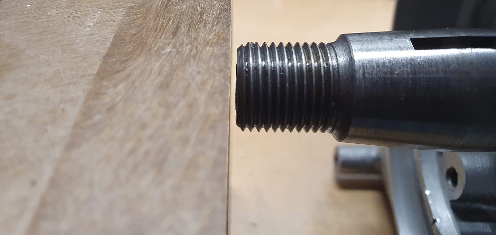
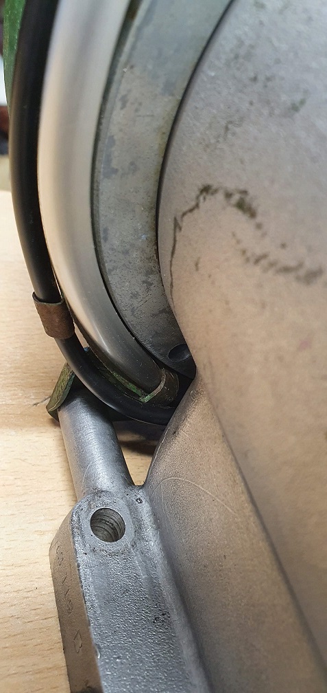
I screwed down the end of my new length of HT lead into the coil and fed it out through the rubber grommet, so that I could refit the stator plate as the points are now nice and clean after removing a fair bi of dirt and pitting. This let me check and set the ignition timing. There was a scored mark on the stator plate indicating a timing mark, not sure if from factory or someone that serviced it at some point, however it seemed a little off by watching the piston at TDC and the distance BTDC that the spark should generate. I believe the original mark was made by someone that assumed the TDC position of the piston was level with the top of the cylinder, however with this particular engine, the piston at TDC stops somewhat short of the top of the actual cylinder. I measured .125" backwards from the highest point that the piston actually gets to at TDC and made a new timing mark on the stator plate
Original mark shown here, and stator plate in new position before marking it

Checked the points gap and reset to .018" and double checked the timing again and all good.
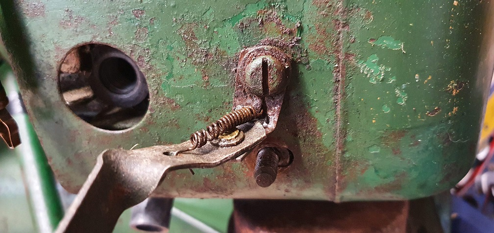
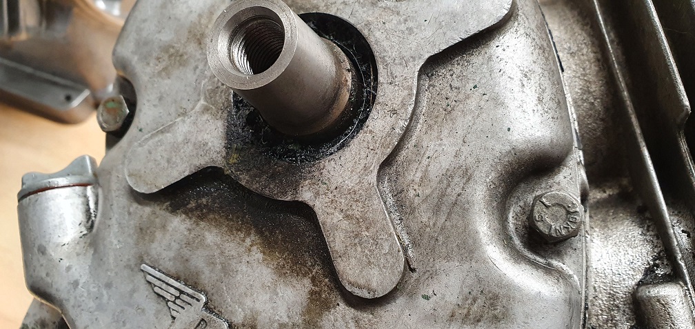
While sorting out the valves and the broken extractor in the other engine, I started giving the rest of the mower a quick once over to check for any other missing parts and spotted that there is, what I believe to be, a grub screw missing from the clutch drive shaft
Does anyone happen to know the dimensions and thread type of this grub screw so that I can try and source a replacement? I couldn't locate it on the parts list for the Marquis MK4 on this site.....
, a grub screw missing from
, a grub screw missing from the clutch drive shaft
Are you referring to the one in the boss of the clutch drum (ring)?
If so,GSF2020JE
Best find someone with an assorted box of imperial grub screws.
Great, thanks - yes that's
Great, thanks - yes that's the one, sorry for the poor description! With that part number, I can see the grub screw is a 1/4" diameter 28TPI and 5/16" long socket cup point type.
I've found a source of these online for pence so can easily sort a replacement out
I removed the 2 clutch shoe
I removed the 2 clutch shoe mounting posts so I could give them a clean up, after wiping and trying to get off some of the old stuck on gunk with them in situ. The shoes didn't rotate very free on the posts, so a quick run over with some fine emery, whilst mounted in my drill, brought them up good and the shoes now rotate nice a free/smooth on the posts
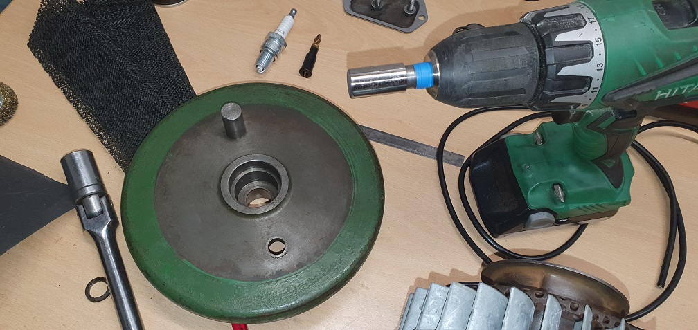
Question - when refitting the clutch flywheel to the crank, does the tape fit get re-assembled dry? Or should the tape be wiped over with grease/oil/anti-seize to prevent any moisture ingress/ease any future removal?
I think someone has stolen
I think someone has stolen your 'r' key LOL
I had to read it twice before I understood it and no, never put any type of lubricant on a taper, you will never get it tight enough to stop it slipping, just assembly it dry.
Oops! Yes definitely a key
Oops! Yes definitely a key missing and not my fat fingers..... let me try again, taper - aha it was autocorrect to blame!
OK thanks, dry fit it is. Any idea about how much torque to apply to the securing screw on the end? The flywheel nut is 30 ft lbs so guessing a similar figure on this end?
Getting things back together
Getting things back together again - valve faces ground and cleaned up and a quick lap, valve clearances set
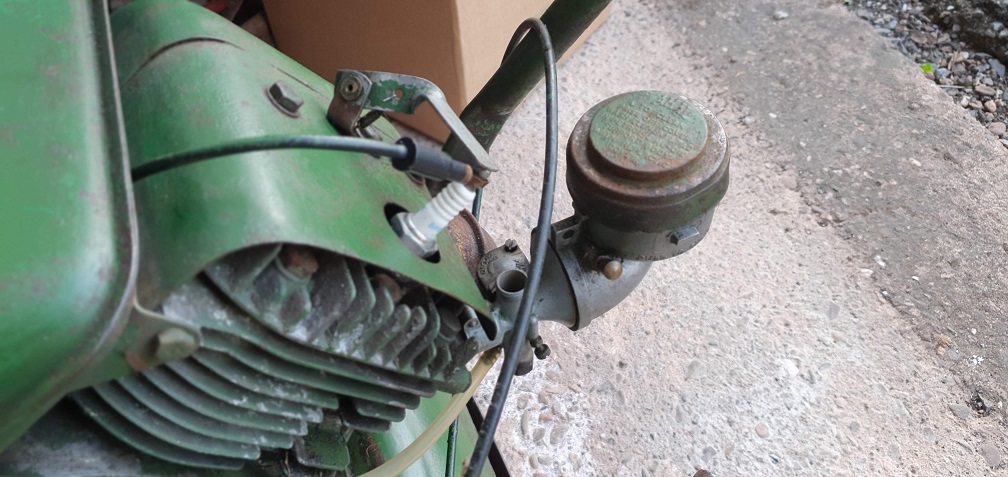
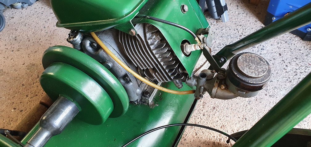
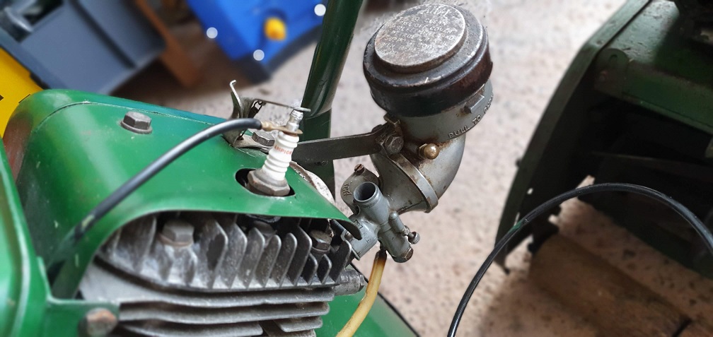
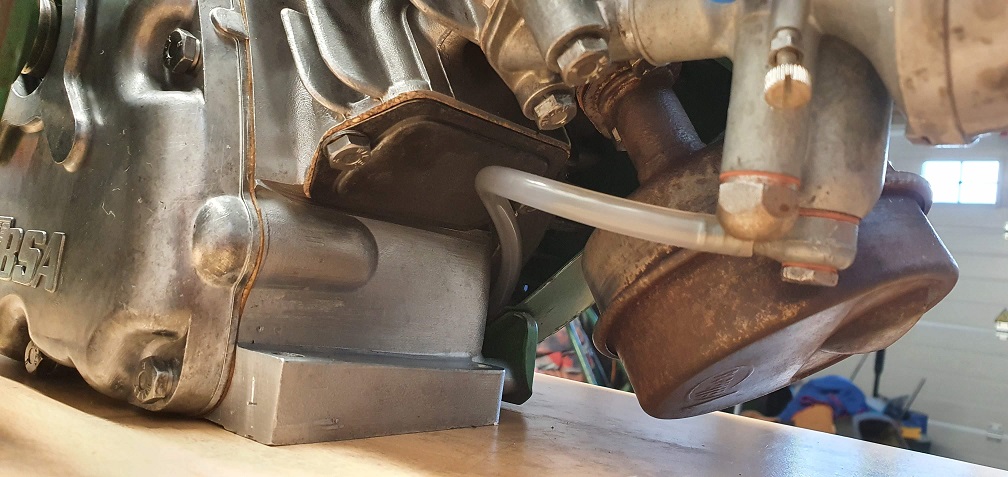
With the valve chest cover not having a fuel pipe support on this engine, it must have sufficient clearance for the fuel pipe - provided the fuel banjo is pointing away from the exhaust at the correct angle
With the valve chest cover
With the valve chest cover not having a fuel pipe support on this engine, it must have sufficient clearance for the fuel pipe - provided the fuel banjo is pointing away from the exhaust at the correct angle
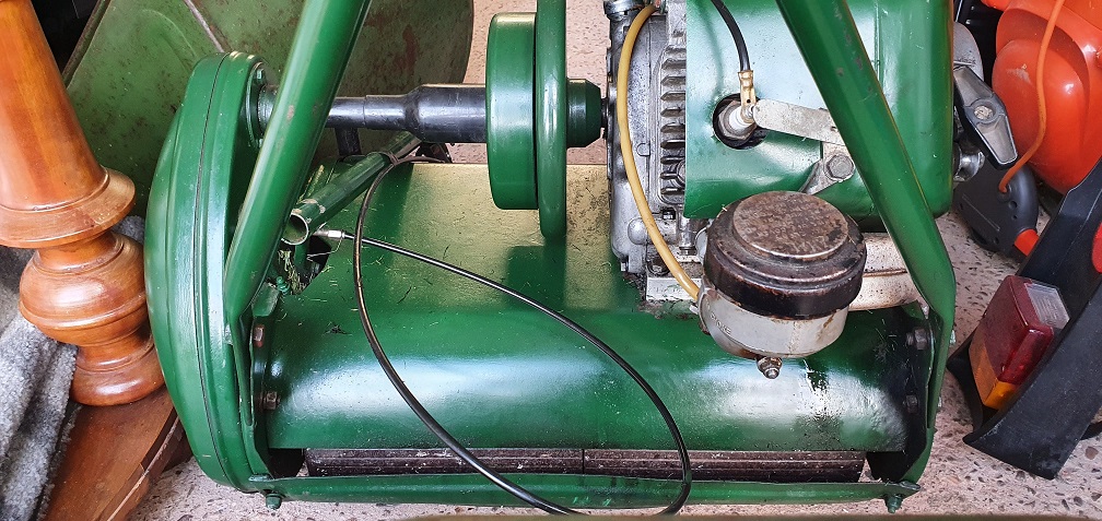
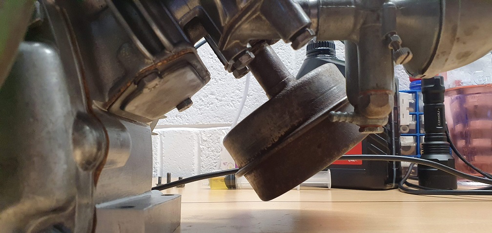
On that engine, with no valve chest bracket, is the fuel pipe still routed around the underside of the flywheel in clips on the cowling ?
It is indeed - and what fun
It is indeed - and what fun it is routing it correctly! Ensuring that the clips are sufficiently wide to allow the snug fitting hose, while not squashing it - or catching on the flywheel rim
Nice rebuild, take your time
Nice rebuild, take your time and do it all just once, no mistakes.
Wish I'd seen your silencer before, I had my grit blast cabinet going this week and could have got rid of all that oxidisation for you. It's all packed away again now.
what fun it is routing it
what fun it is routing it correctly! Ensuring that the clips are sufficiently wide to allow the snug fitting hose, while not squashing it - or catching on the flywheel rim
As you say; and possibly the reason that on many Slopers that come my way the pipe has been routed under the fuel tank, and worse still the original clips broken off or hammered flat. I have also seen the cowling assembled with spacer washers between it and the crankcase to increase the clearance.
Very occasionally I’ve seen a Sloper with a hard, black plastic, thin wall fuel pipe which, I assume, was the original factory fit. It needs to be warmed up to release it from the tap and banjo , but if it’s done carefully, it can be reused. The off the shelf PVC 3/16” id tube has to be carefully squashed under the clips.
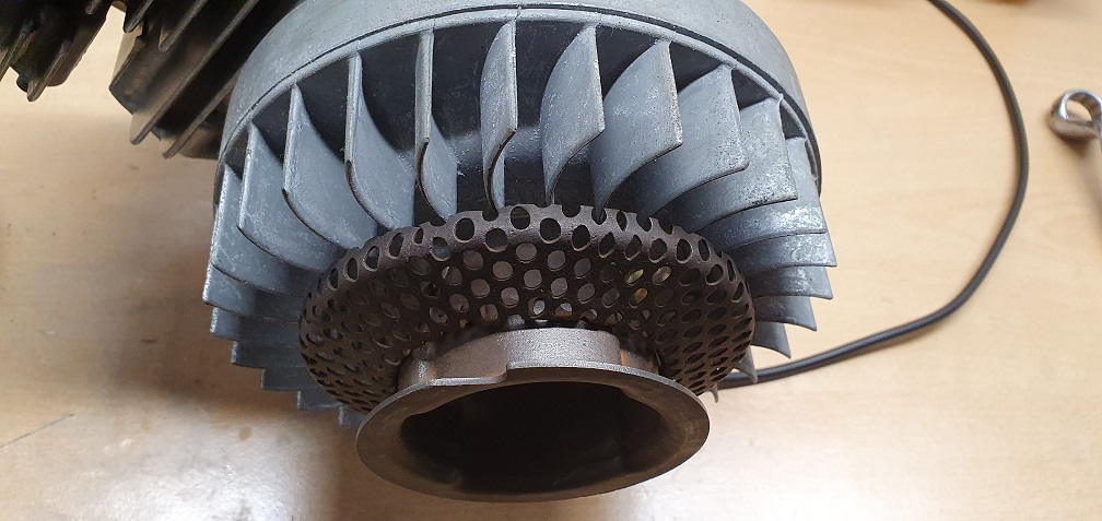
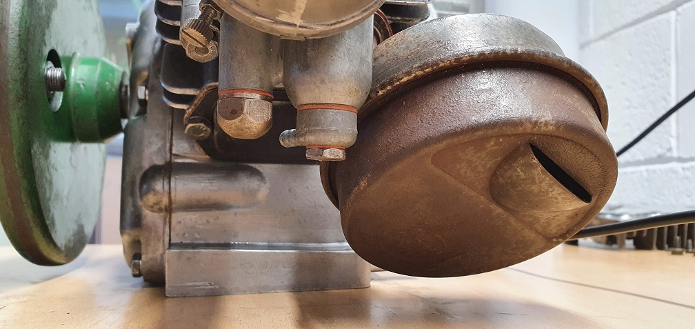
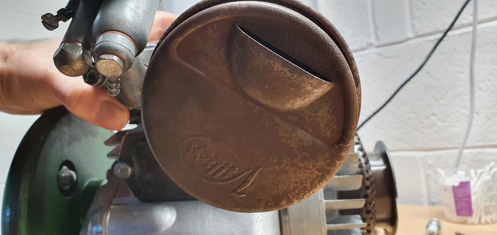
The silencer in your image is a late pattern one, the original would have been more rounded with a short stubby exit pipe and were either just plain bright steel, or, possibly had a silvery coating of some sort but it soon discoloured or corroded. On a working machine, I bead blast, warm up in the oven, spray with Barbecue Paint and then bake in the oven before refitting.
Ah a blast cabinet is
Ah a blast cabinet is something else on my never ending and ever expanding wish list! I'm sure it would get a fair bit of use with various things that I seem to end up restoring. Not sure I could find the space in the garage, although I have seen the table top sized cabinets that sit on the workbench, which would cater for blasting small parts at least.
Regarding the fuel pipe, it was routed incorrectly on both of my engines, but I can understand why so many owners would do that when replacing the fuel pipe - a shorter and easier route to take. I had to use a longer length of 3/16 ID pipe to follow the correct routing through the cowling.
Interesting to hear about this silencer being a later pattern one - I've just checked the silencer on the other engine and it appears that it could be the type you are referring to, with the stubby exit?
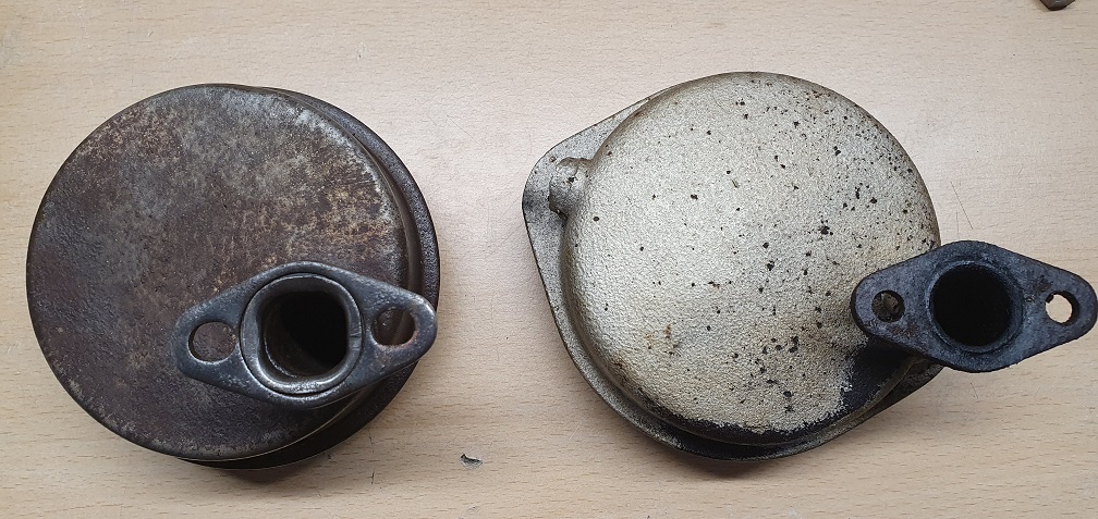
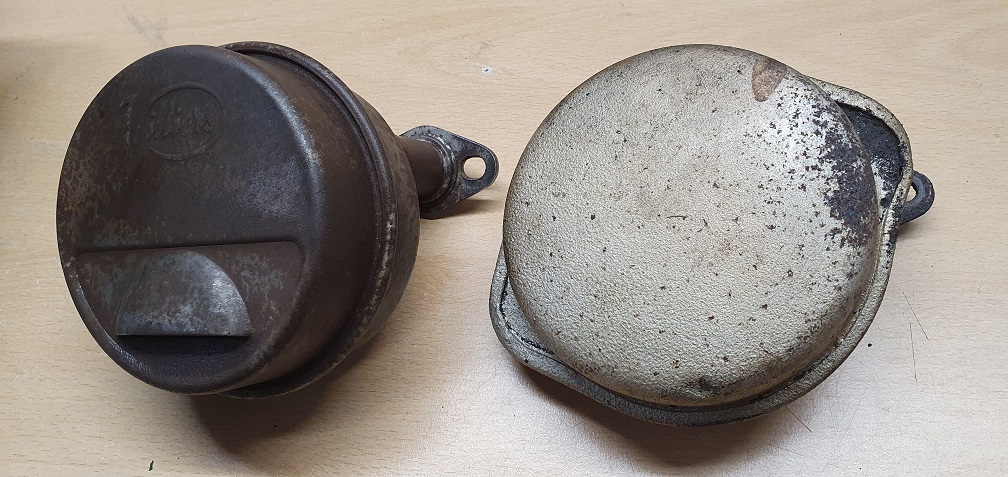
If that's the correct style, then I'll swap them over. I'm not sure how stubby the exit pipe would be when new, as it appears the end of the pipe has corroded away so I'll neaten it up a little.
I did promise myself that I wouldn't paint these 2 mowers after doing the paintwork on my Suffolk, and instead leave them 'as is' and just clean up the existing metalwork/paint as much as possible, while ensuring they are fully mechanically overhauled. I already broke that promise when I painted the Amal carb air intake covers as they looked a bit sorry for themselves. Perhaps I could extend that to just doing the exhaust silencers as well. I have some very high temp silver spray which I used successfully on the Suffolk exhaust and it came out well. This other silencer has had a coat of some sort of silver paint in it's life, so perhaps I will clean both up with the wire wheel and then coat them in that paint......
Yes, that’s the period
Yes, that’s the period silencer . Nearly all the ones that I see are a bit dog eared. I think that your “wrong” one was of later manufacture and was never original on an F12 Sloper but was original on the A15 and with a longer inlet pipe on the C30, F15 and C12.
Thanks for the info. The
Thanks for the info. The parts manual lists 2 different numbers for the silencer on the F12, I wonder why? It says "87-1722 or 87-1724"
Given silencers don't seem to crop up very often - since I've been looking for parts at least - I may have to stick with the Villiers embossed 'incorrect' one. I think I'll put that one on the newer mk4a though. It's in good shape other than the oxidation so some high temp stove/bbq paint will hopefully help to preserve it. I'll give the flange a clean up just to flatten it a bit while I'm at it.
A spare shoe string soaked in
A spare shoe string soaked in petrol done the business, followed by compressed air, due to a lack of a (much more suitable) pipe cleaner! At least, I think it was a spare.......
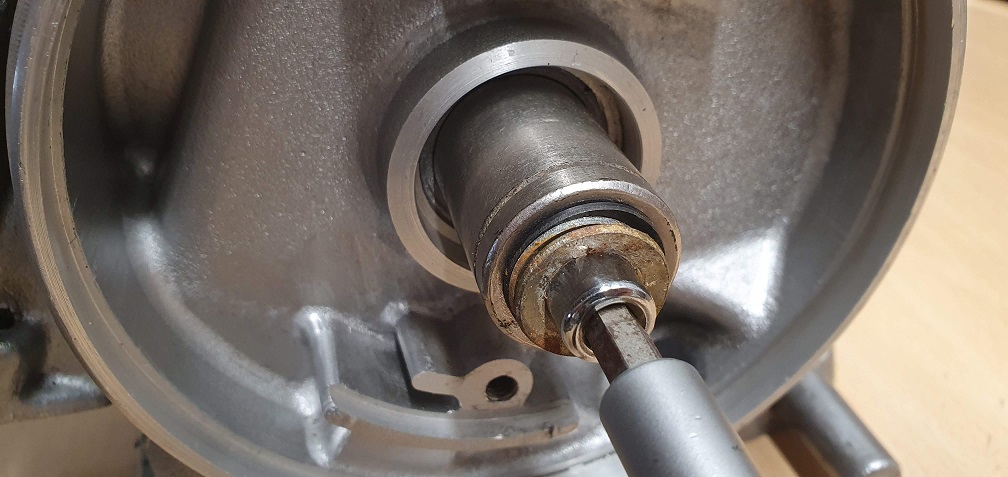
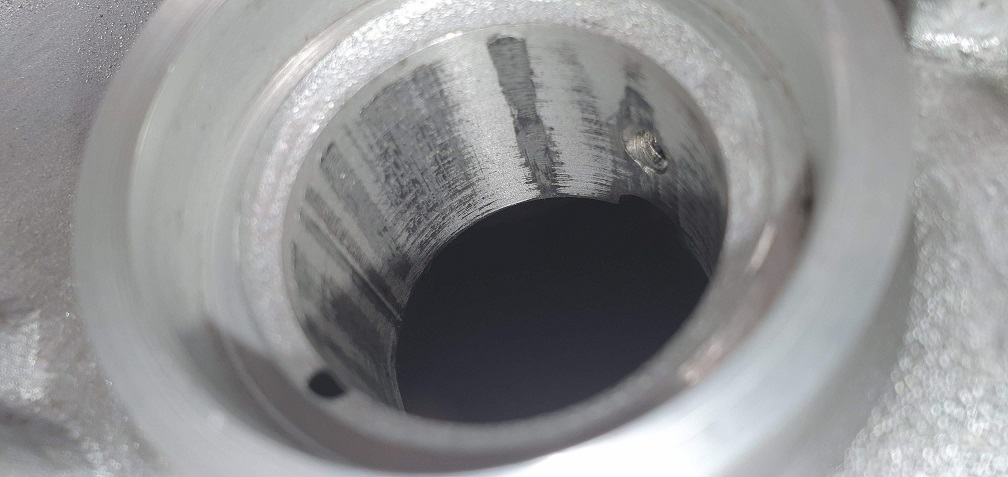
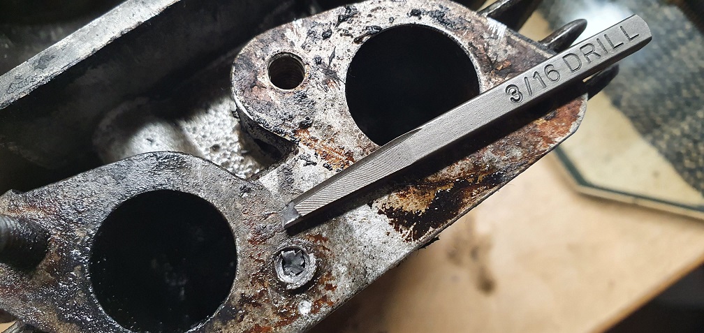
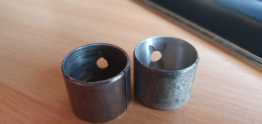
It seems the crankshaft bushes are slightly different in size to the ones you are working with DJD, my crank journal diameter is .9990" so I THINK I will need a bush with internal diameter, when fitted, of 1.000". I am going to try to make up a suitable press/drift/extractor to remove the badly scored one so I can check the outside diameter when uncompressed as well as the housing diameter, and hopefully I can find a suitable bush on that website. Measuring the length of the current fitted bush shows a reading of .875" (7/8) but I can only find bushes in either .750" or 1.000", so .125" too long or too short. Not sure if the size difference would affect the oil hole position
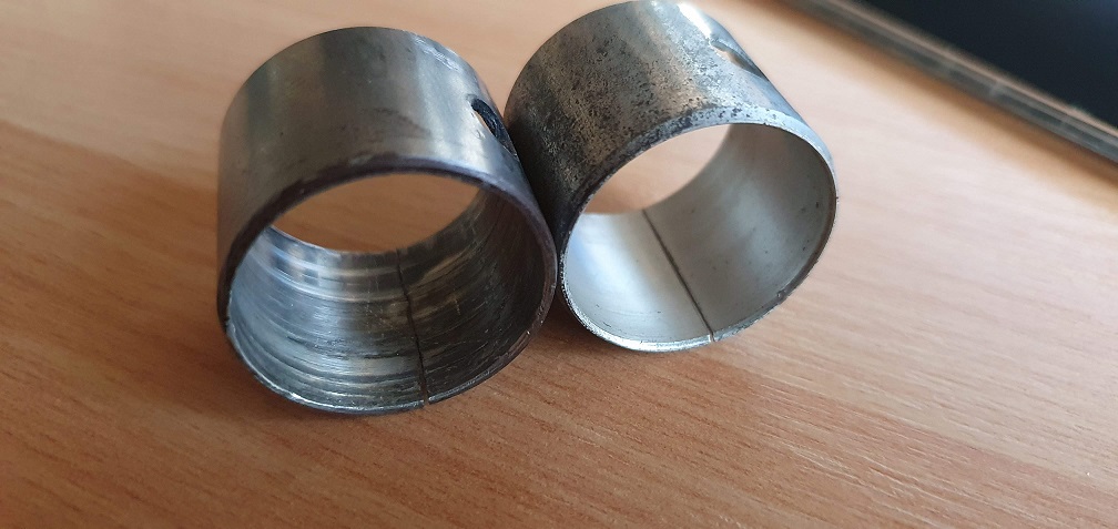
A picture of the drift size required for removal and insertion