Webb 14” Cylinder Mower
Hello all and thank-you for allowing me to join.
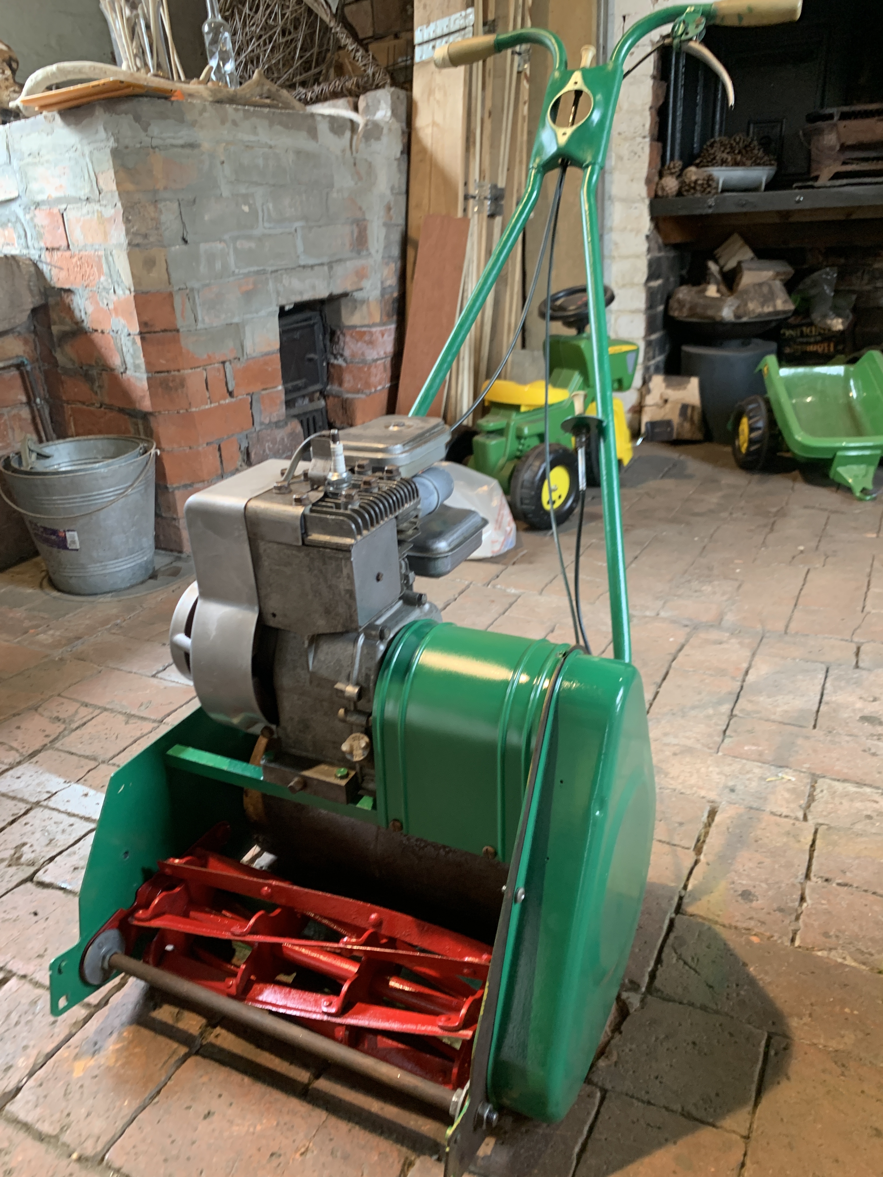
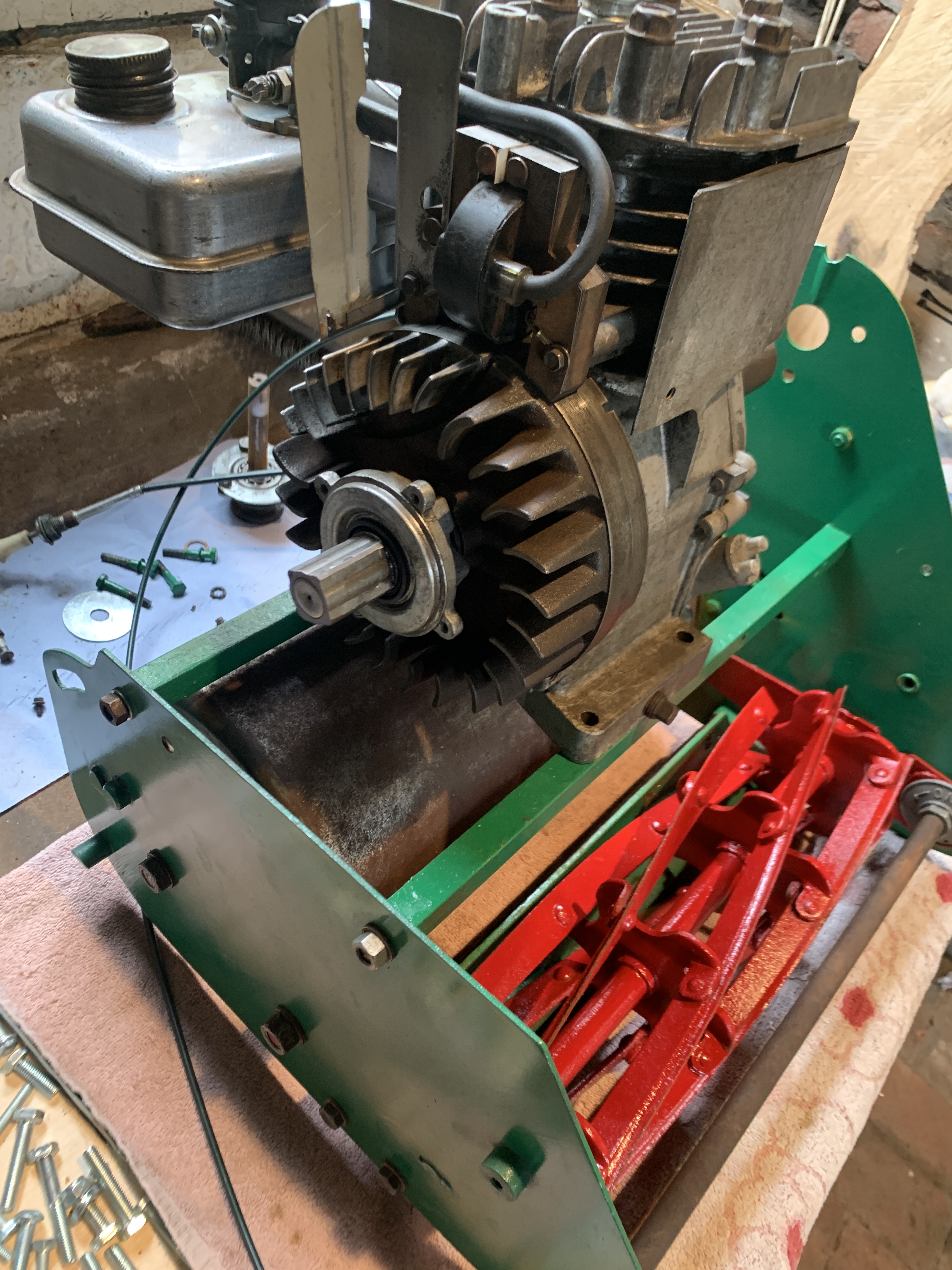
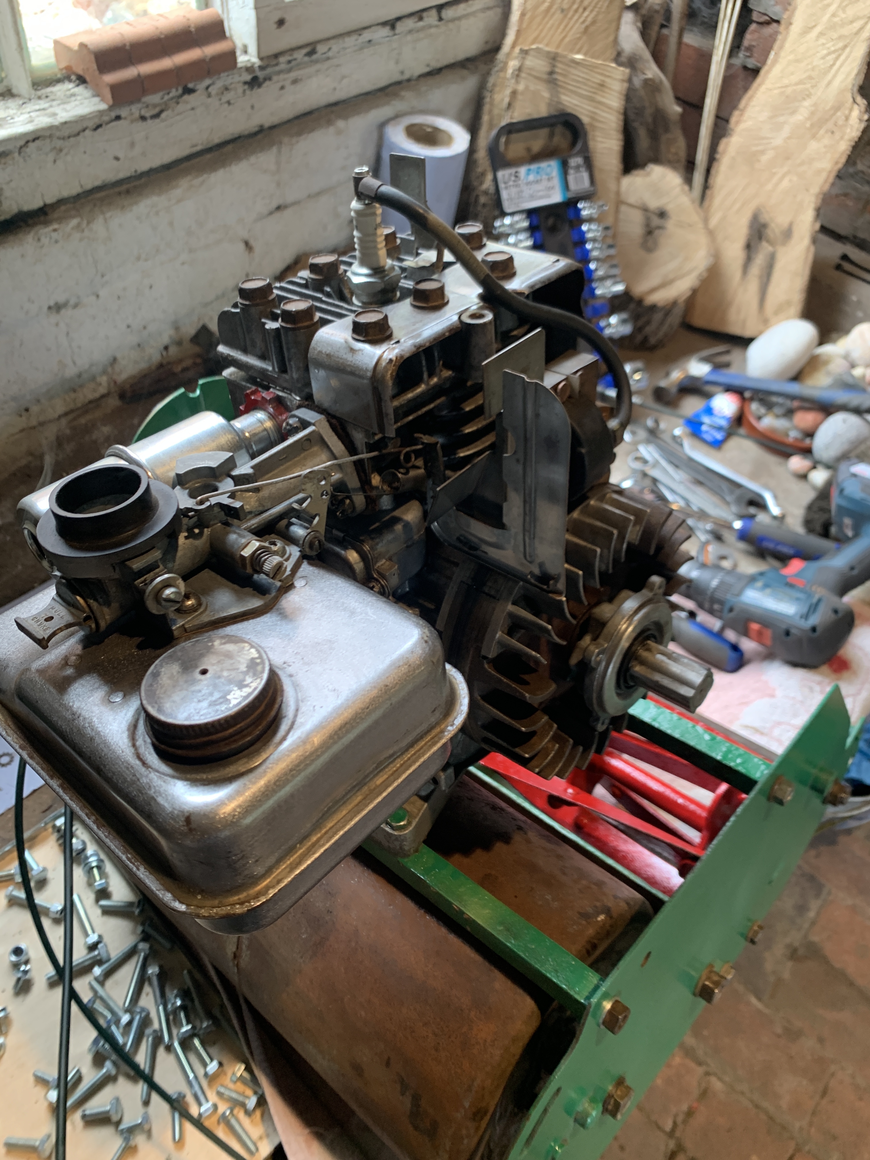
I have found a Webb 14" cylinder mower and started strip and rebuild on Saturday.
The Briggs & Stratton engine indicates it was manufactured Dec 1966.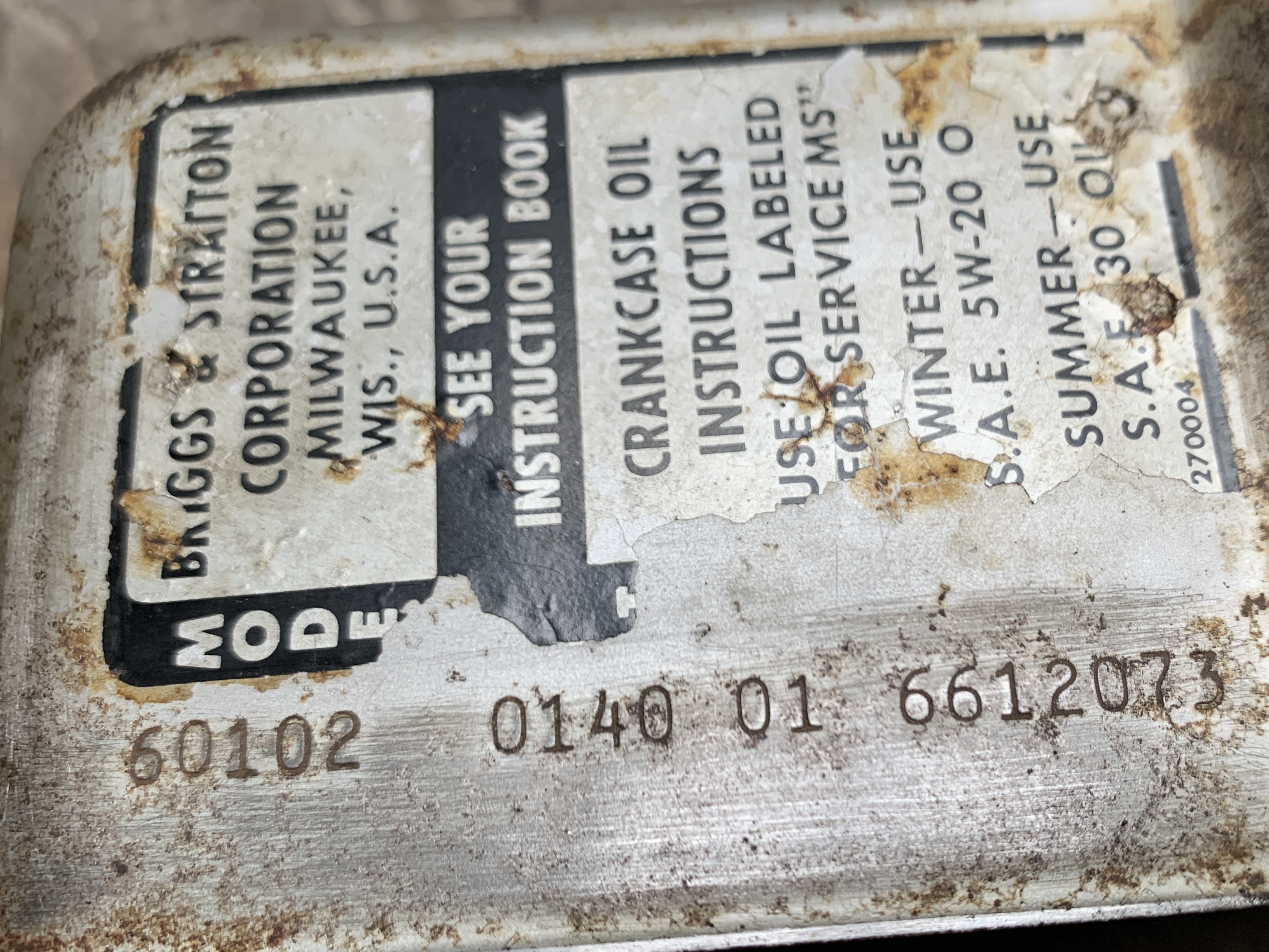 No spark - no surprise the mower looks as if it's been sitting in the long grass for 10 yrs ! Air filter was rotten and fuel tank full of rust. None the less after cleaning spark plug cable connection and spinning it over using my domestic drill I got one spark, and one spark only.
Stripped down to points and after some very casual rubbing with sandpaper, I spun her up again and got weak but consistent sparking.
More conscientious attention to points and a new plug got good spark, so added some clean fuel and again spinning her using my drill got a very poor and rough runner.
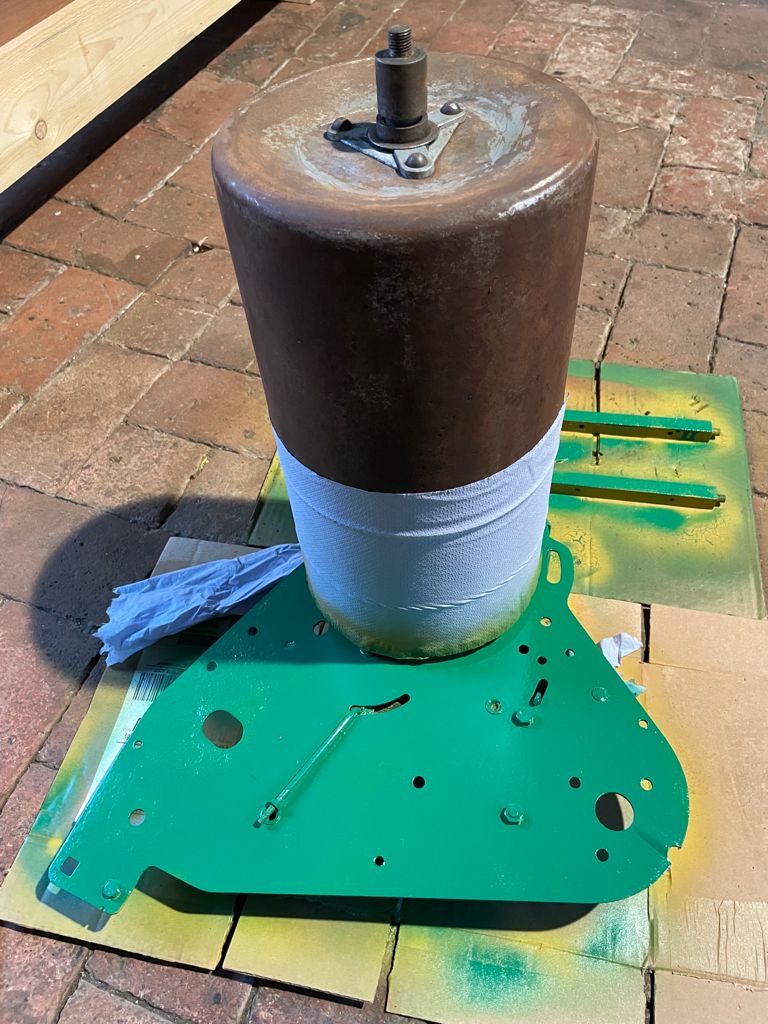
Whilst still running I sprayed some Penetrating fluid into the carb ( no filter ) wow, the engine screamed at crazy rpm. So now I know it's a runner I have stripped completely and am cleaning / restoring / repainting.
5 issues tho;
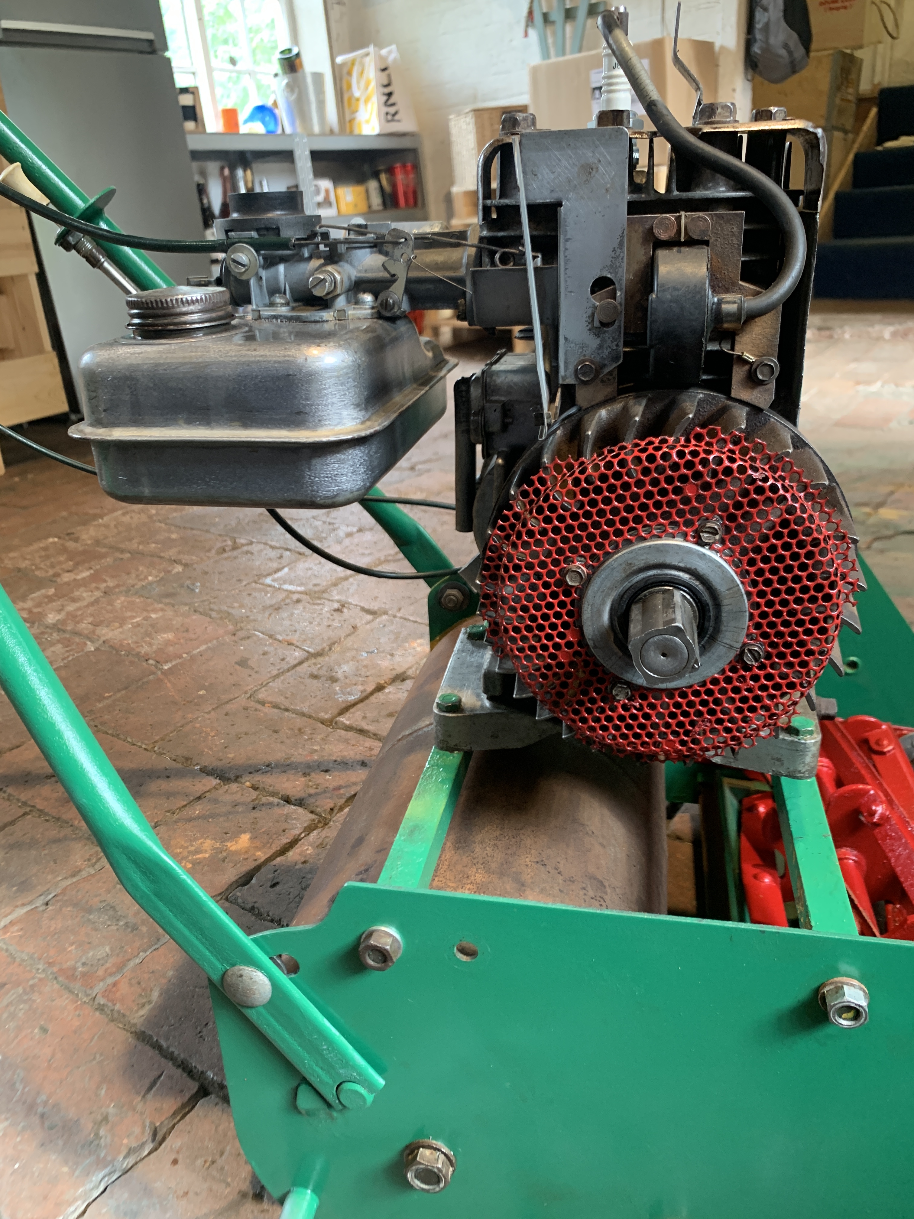
1. I have no idea of model and have not located anything on the mower other than the engine manufacturers marks
2. Blade cylinder bearings are pretty rotten and I have no idea where to start removal / source new.
3. Will need a new drive belt but no idea what I am looking for.
4. Exhaust / muffler threaded part just not coming out, I managed to free off the clamping ring and have read that applying heat is a no no, lots of pen oil , drilled a hole and using a bolt to try to unscrew but no luck so far.
5. need new front rollers.
worst of all I didn't think to take any photos, sorry readers my bad ....
Forums

It's in pieces, I will
It's in pieces, I will reassemble in next few days 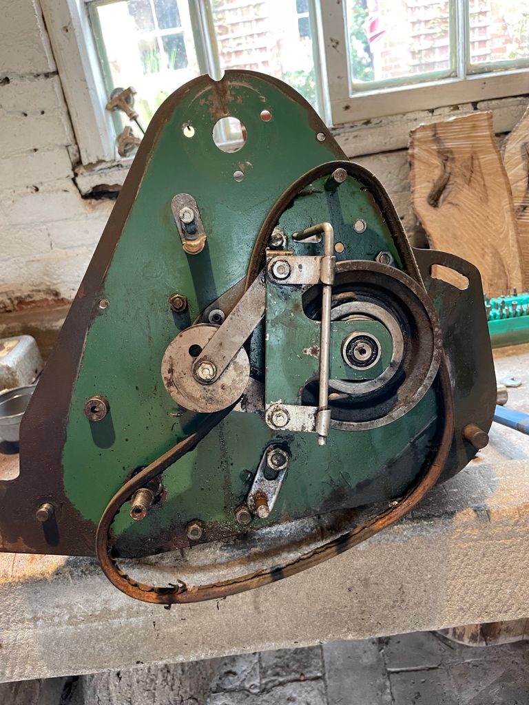

I think it is a model from
I think it is a model from this discussion: Webb identification | The Old Lawnmower Club
Front rollers:
DIY base material: MAGASIN, Rolling pin - IKEA
Finished rollers:
Atco - Qualcast Spares | GLC - Gateshead Lawnmower Centre (jungle-busters.co.uk)
Qualcast/ Atco/ Ransome/Webb/JP Maxees/Honda/Greens Lawn Mower Wooden Rollers | eBay
For a more modern look you could use a roller from AED, as an example: Replacement Roller For A Jacobsen LF3800 Ride On Fairway Lawn Mower | eBay
High Capacity Conveyor Roller 60mm Diameter With M8 Female Thread Fitting (PR60) | eBay
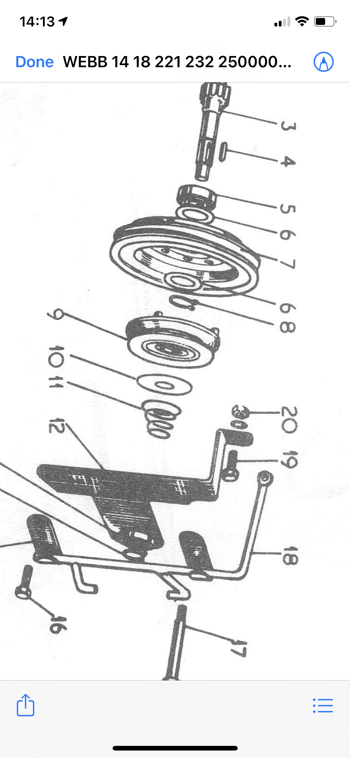
From the drive selector in
From the drive selector in your image and shown on page 70 in the attached Dropbox scan, I think that these are the correct illustrated parts pages . The drive belt is an A36 if that helps.
https://www.dropbox.com/s/447cw2t4tvcmrhl/WEBB%2014%2018%20221%20232%20…;
Wow thanks for the helpful
Wow thanks for the helpful links.
I am struggling with sourcing drive belt and cylinder bearings.
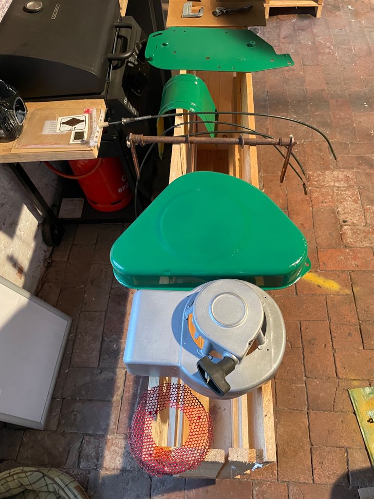
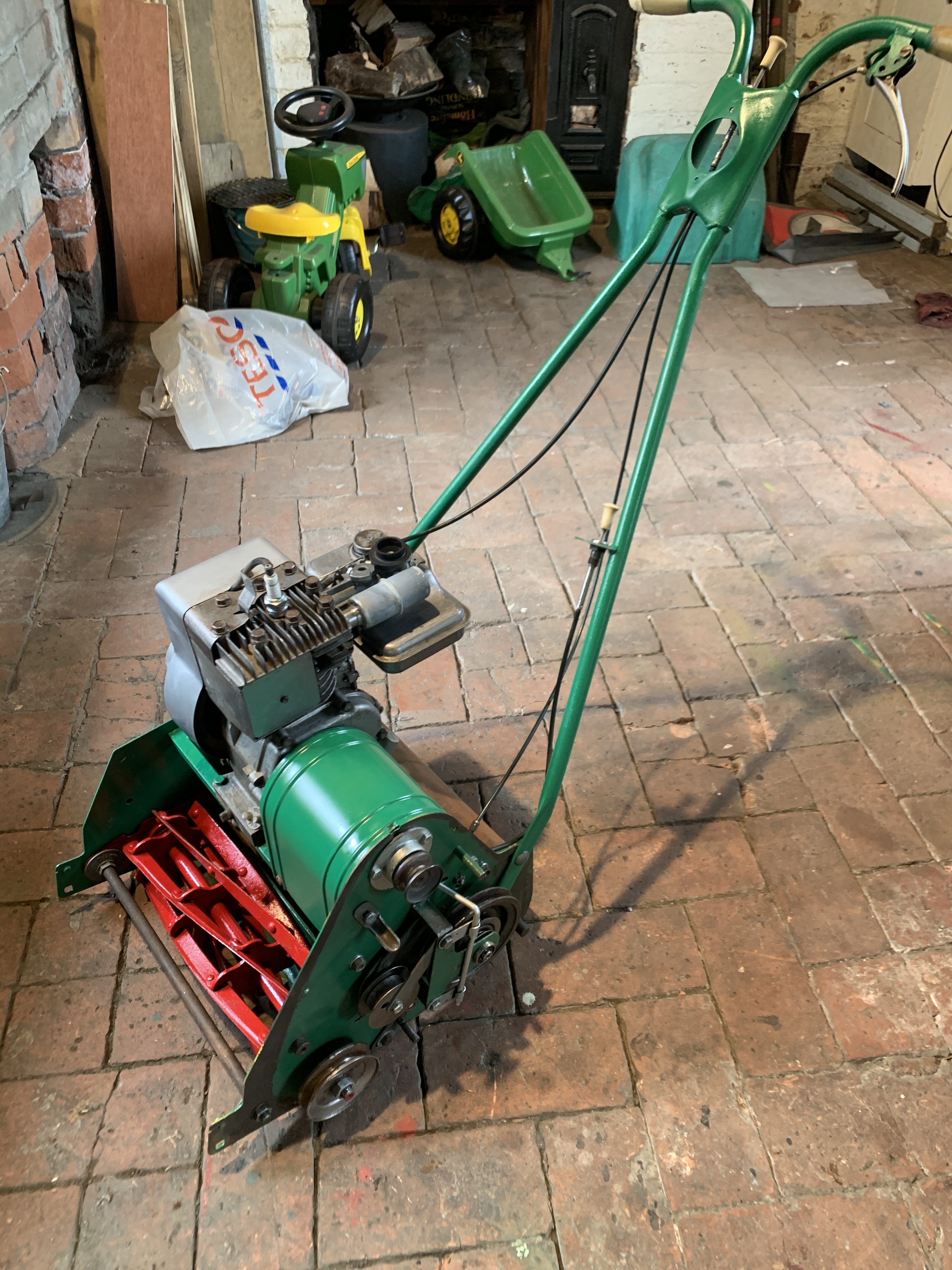
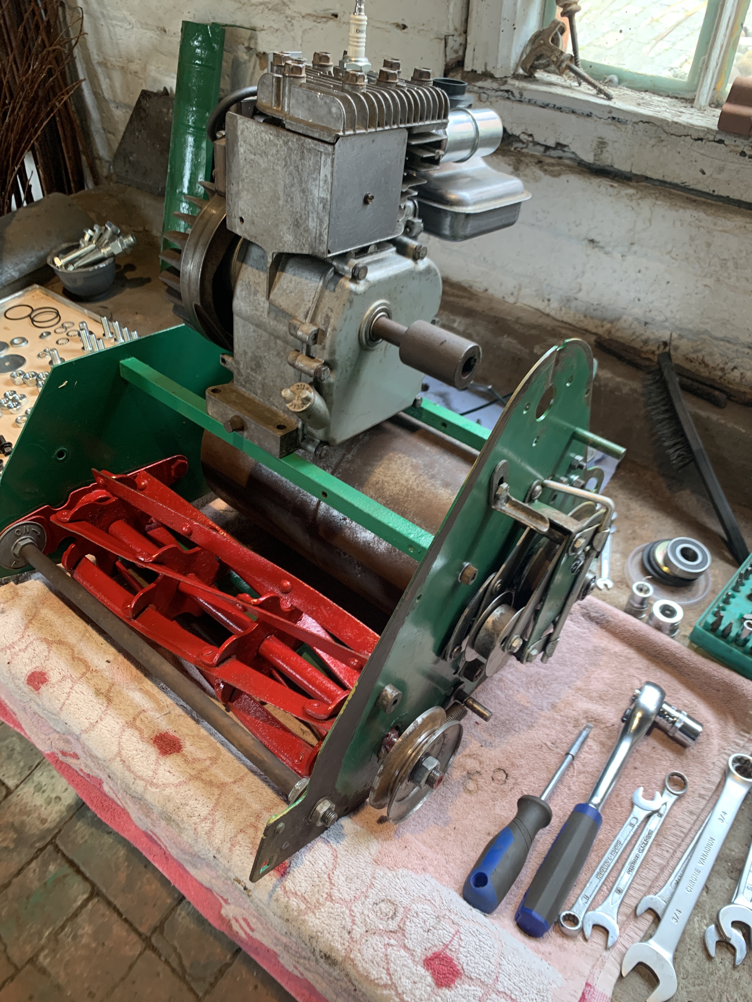
all components have been cleaned and primed / painted or coated with clear lacquer.
Regarding the extraction of the old rotten muffler I am now thinking;
Run up the engine and let it get hot, then attempt exhaust extraction. As previously mentioned I have drilled a hole through it and have inserted a bolt
Hoping that by getting the engine hot I might get lucky and "shock" it enough to unscrew
still really regretting not taking any photos pre-dismantle - doh !
Memory says that the bearings
Memory says that the bearings are self aligning RL5s or the equivalent (KLNJ 5/8 ???) . Screwed in exhausts can be difficult ( the polite version). Failing you present efforts this will work . Cut the exhaust through parallel and about 5/16” away from the block. Take about 4” of new hacksaw blade , wrap a few turns of masking tape over about 2” for something to grip. Insert the blade into the exhaust with the teeth facing outwards and pull it towards you. Continue doing this until you have cut through the pipe. Don’t be over concerned about some cut into the block. Using a hammer and substantial punch or vice grips on the bit that you left proud of the block you can curl the pipe lengthwise inwards and the rest will loosen up. Worst case you might have to make another cut opposite the first so if the first was at the bottom downwards, take the cylinder head off and turn the engine upside down for the second.
Never failed me yet !
Exhaust extracted - happy
Exhaust extracted - happy days
Good progress this evening
Good progress this evening 
Well that was fun.
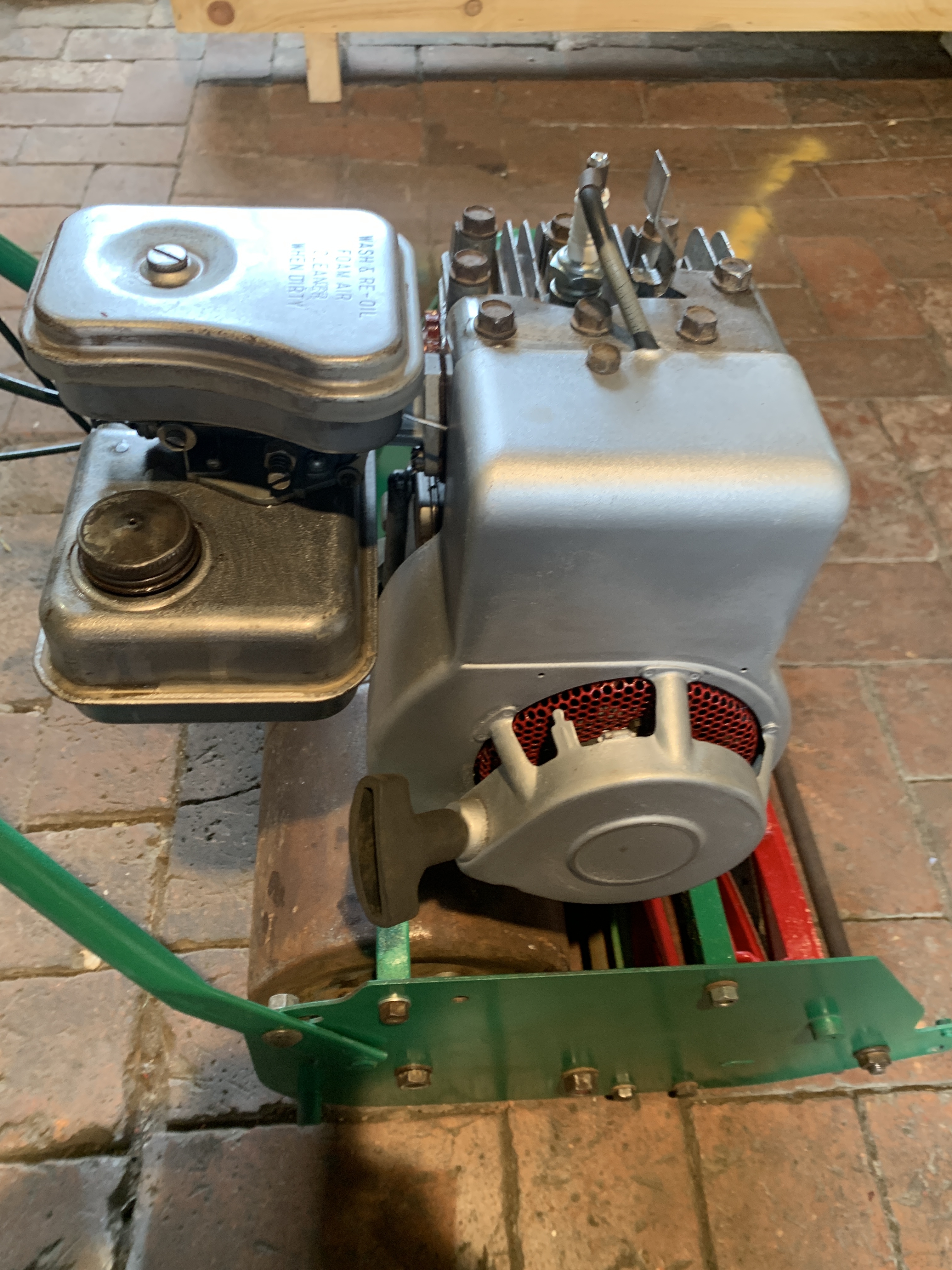 Well that was fun.
starts easy
just need to fabricate roller ( sourced donor from kitchen dept at Dunelm )
Well I have started an run
 Well I have started an run her every day and the starting / running gets better every day.
Still need to fabricate a new front roller.
But....
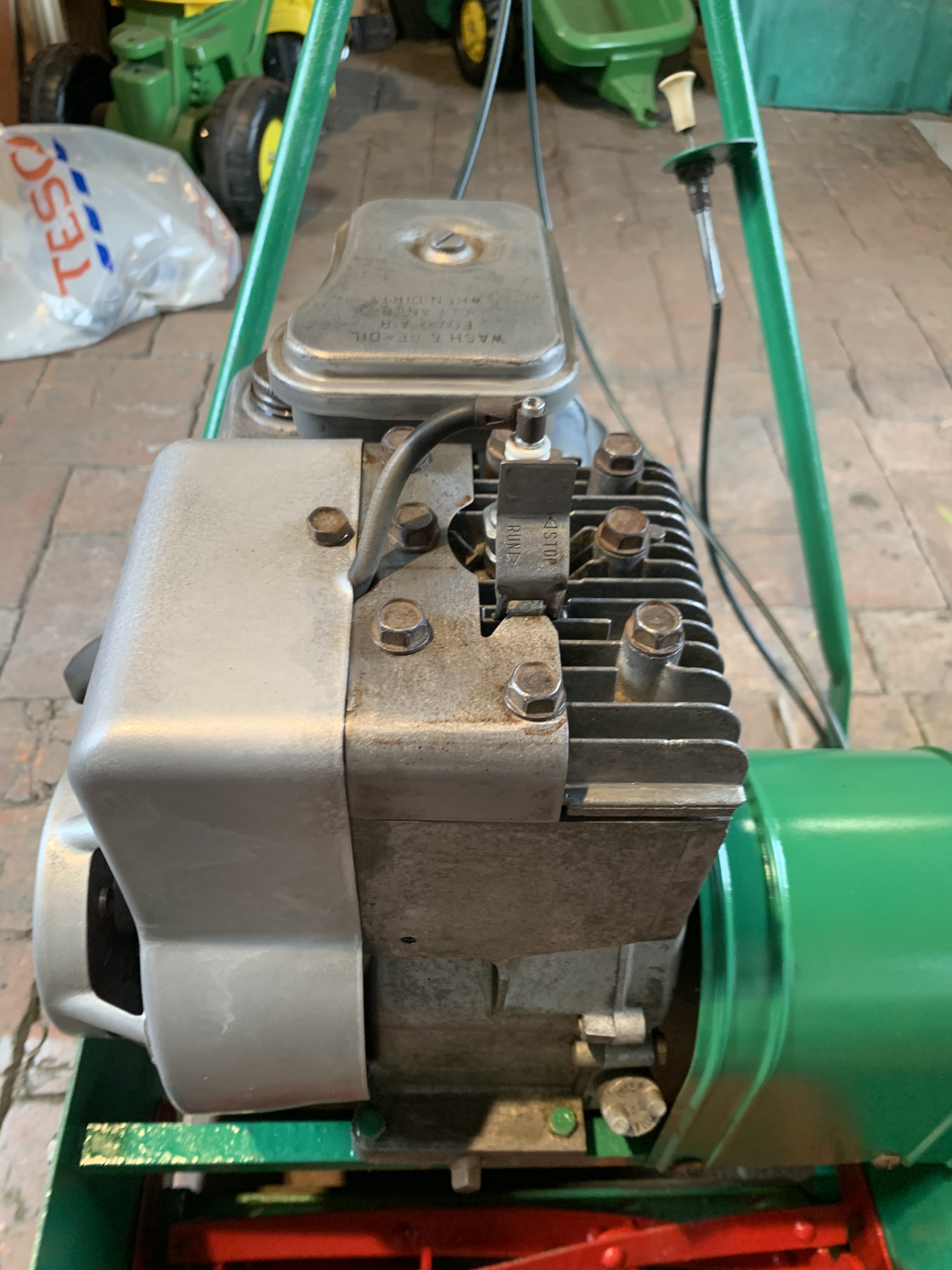
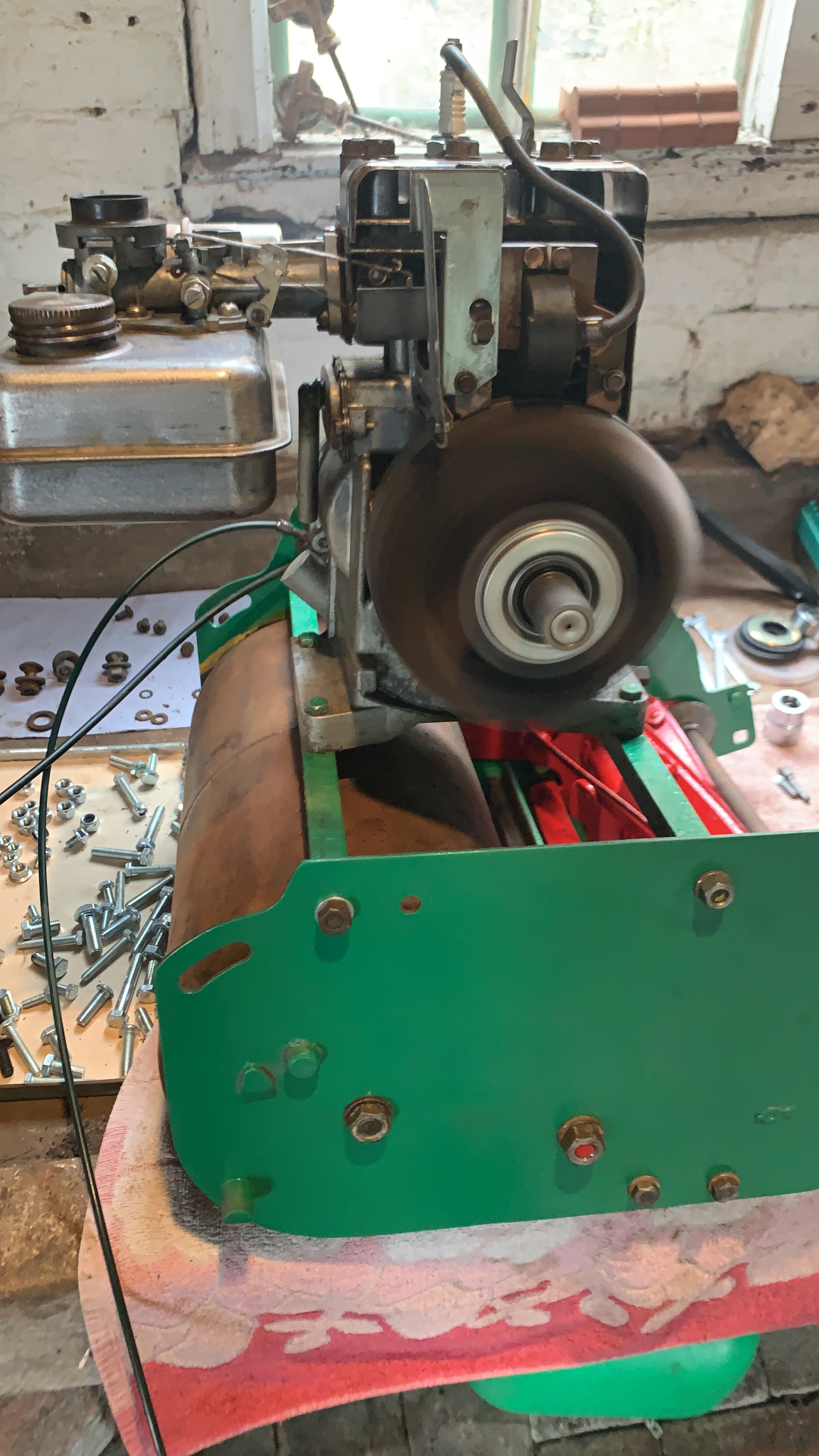
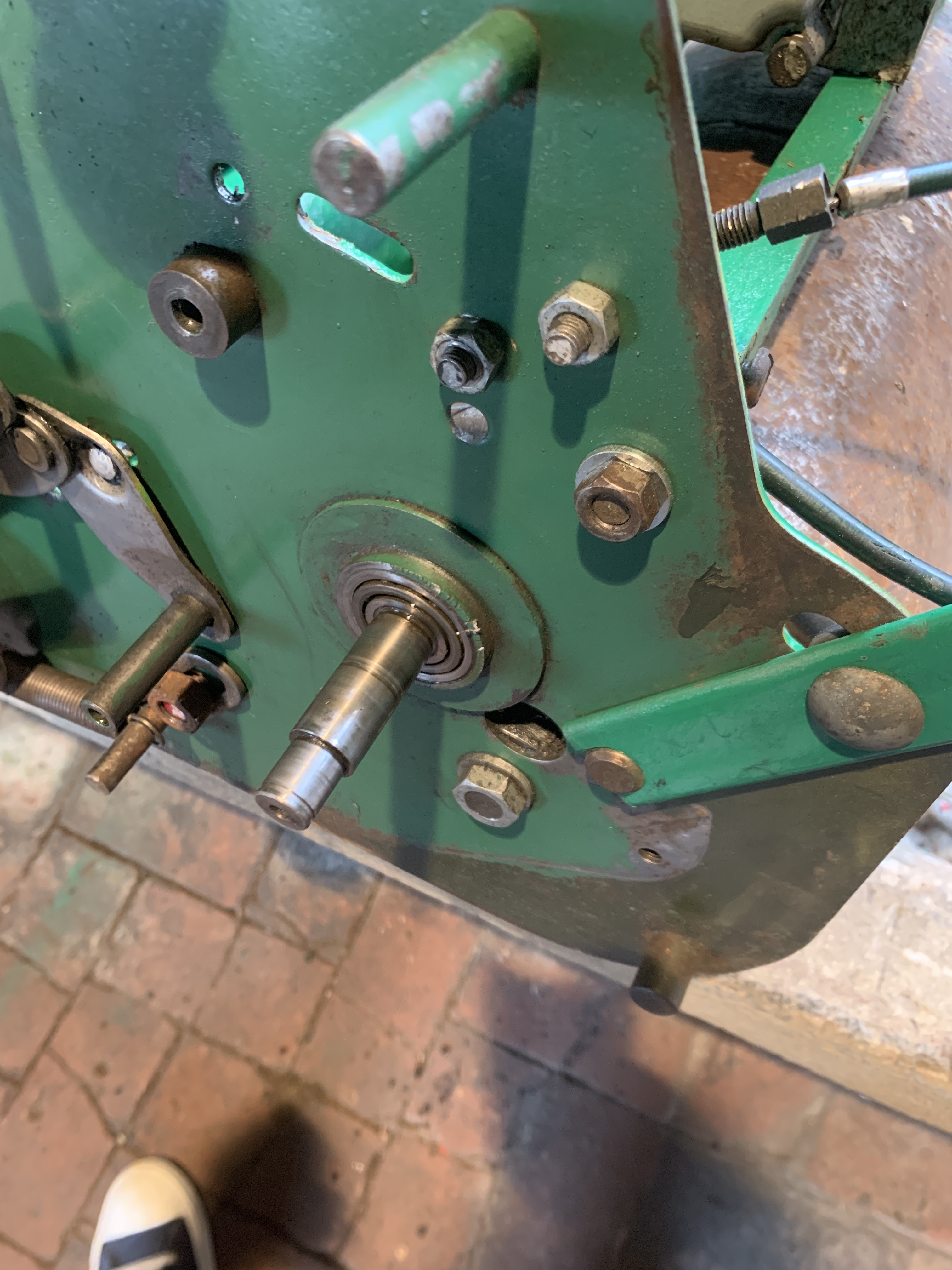
Drive engagement for rear roller is pretty much non -functional when engine running.
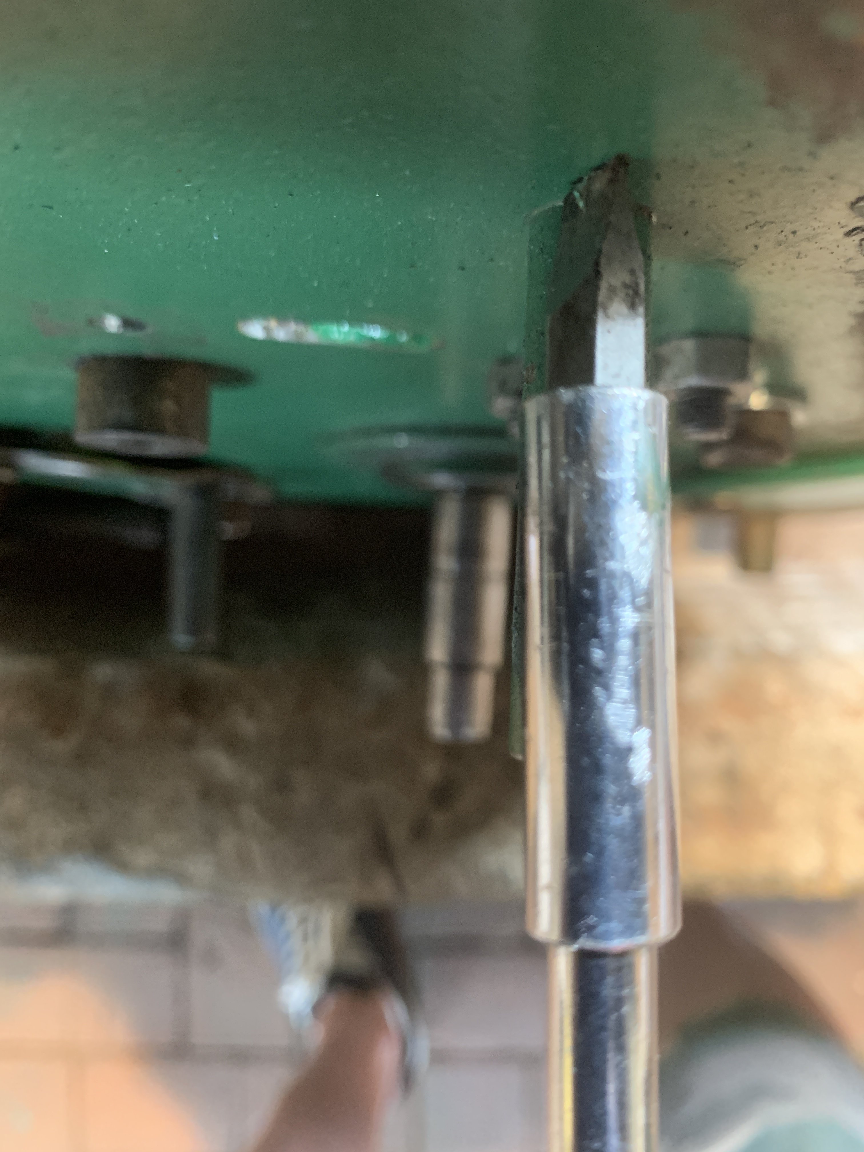
The main pulley wheel is wobbling all over the place when engine running.
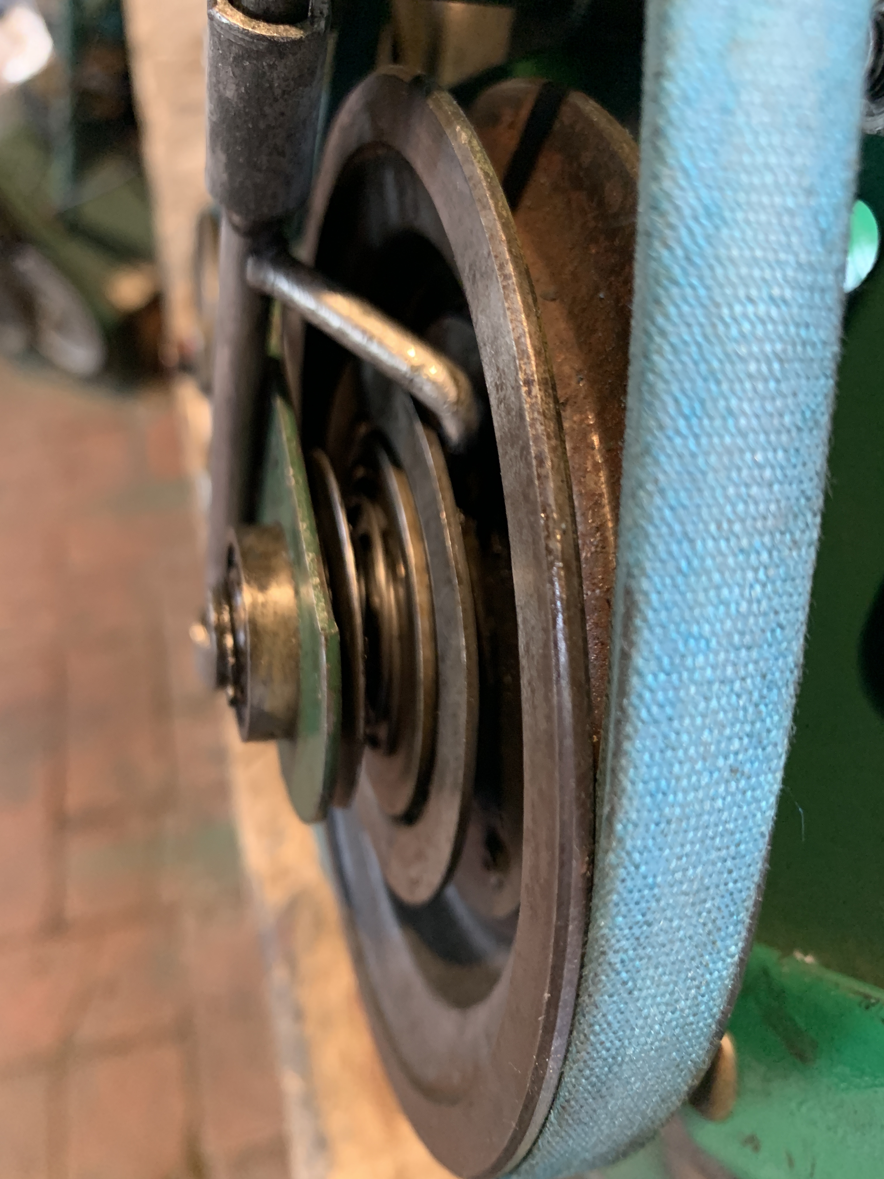
This image shows that the shaft has approx 5mm play But I do get good engagement of gears with roller so I suspect it's just the bearing that's the problem ?
Does anyone know if I can change the bearing without dropping the rear roller out ?
what bearing do I need ?
thxs
From your image it looks as
From your image it looks as though the pinion bearing is fitted from the inside but as far as the pinion shaft wobble is concerned, is the outboard end not supported by a bush in that triangular bracket when all is assembled holding the shaft more or less rigid? Item 37, support bracket pinion shaft, 38, bush for above.
Unfortunately the parts book is not at all clear as it shows parts for both the 14 and 18” versions together date dependent variations. Also I’m not clear from your one image of the rear roller whether it’s single piece or double. If it’s a double, the pinion will be driving a ring gear on the central shaft which will carry a ratchet wheel engaging pawls on the outer ends of the rollers. If those pawls are stuck or their springs broken , no drive will be transmitted to the roller sections. The book suggests that arrangement may be confined to the 18” machine . By the looks of it the 14” machine will have a ring gear fixed directly to the single roller drum.
I think that you will need to dismantle the frame and roller before all is revealed . As far as I can remember the ring gears are a cast alloy part and do wear, leading to loss of drive.
EDIT . Found another parts book that makes it clearer that you should have a one piece roller, so forget about all the ratchets and stuff - just a ring gear fixed to the roller itself. So the options for no drive are -
A problem with the pin clutch behind the belt pulley.
Worn pinion or ring gear teeth - inspection will need the removal of the roller.
The list is not helpful with a bearing size, just Webb’s part number but I’m guessing an RLS52ZZ - that’s a 5/8” bore rigid with two steel seals.
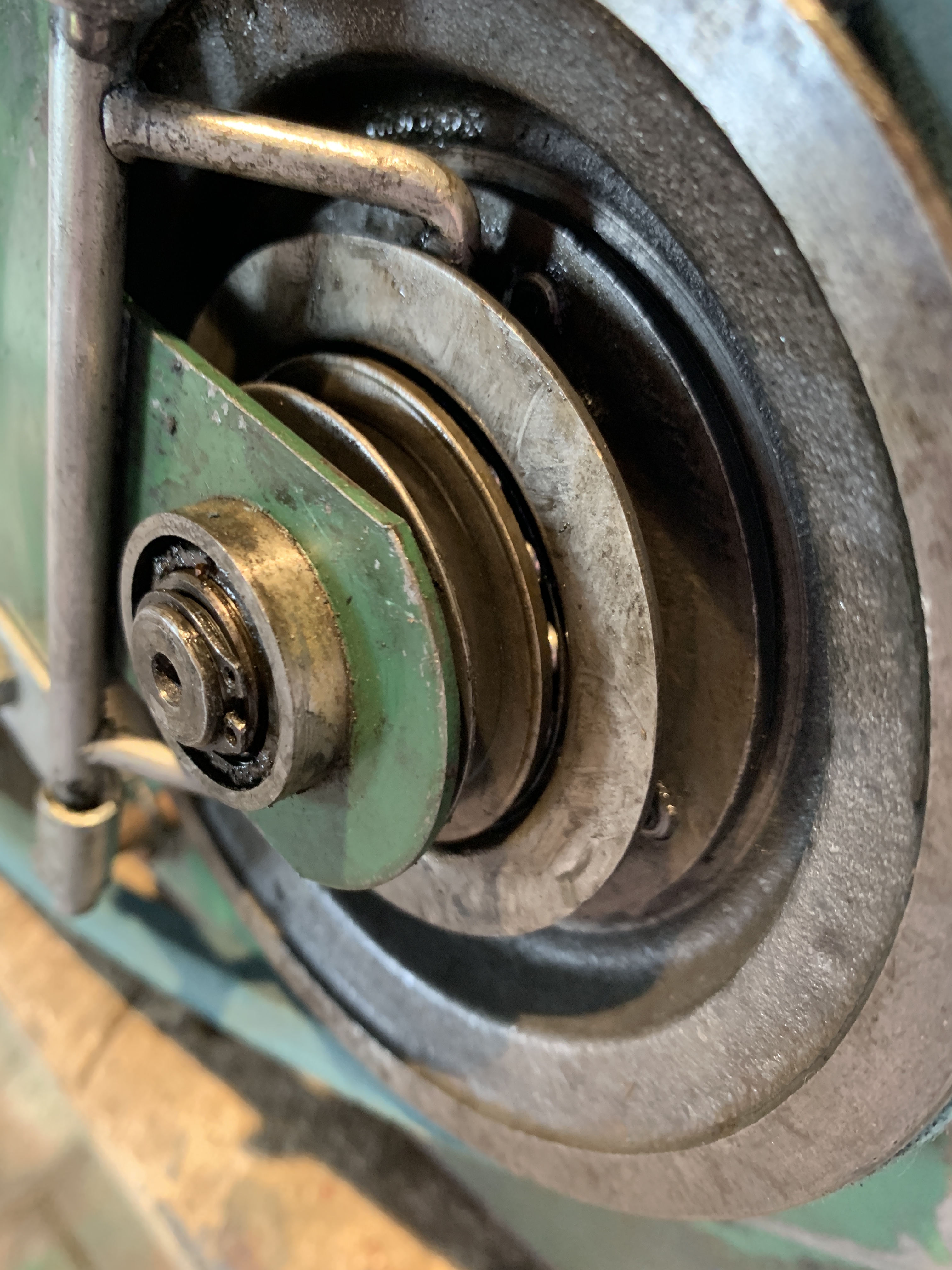
Thanks for your reply /
Thanks for your reply / further info. Yes you are correct the small frame supports the shaft. However further examination reveals that the pulley wheel is sloppy (wobbles) on the shaft itself 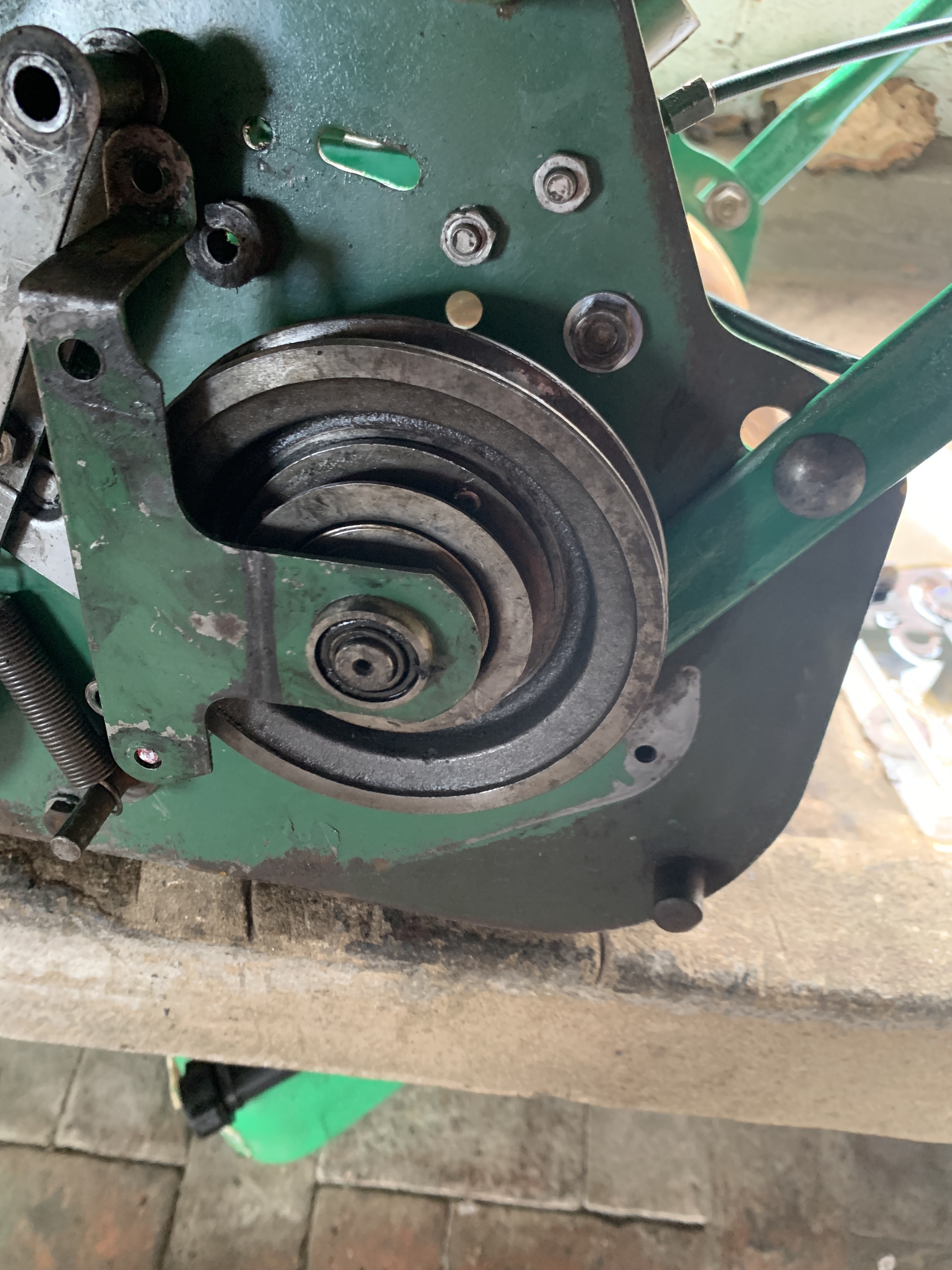
Reassembled and now get
Reassembled and now get momentary drive to the "land roller" .
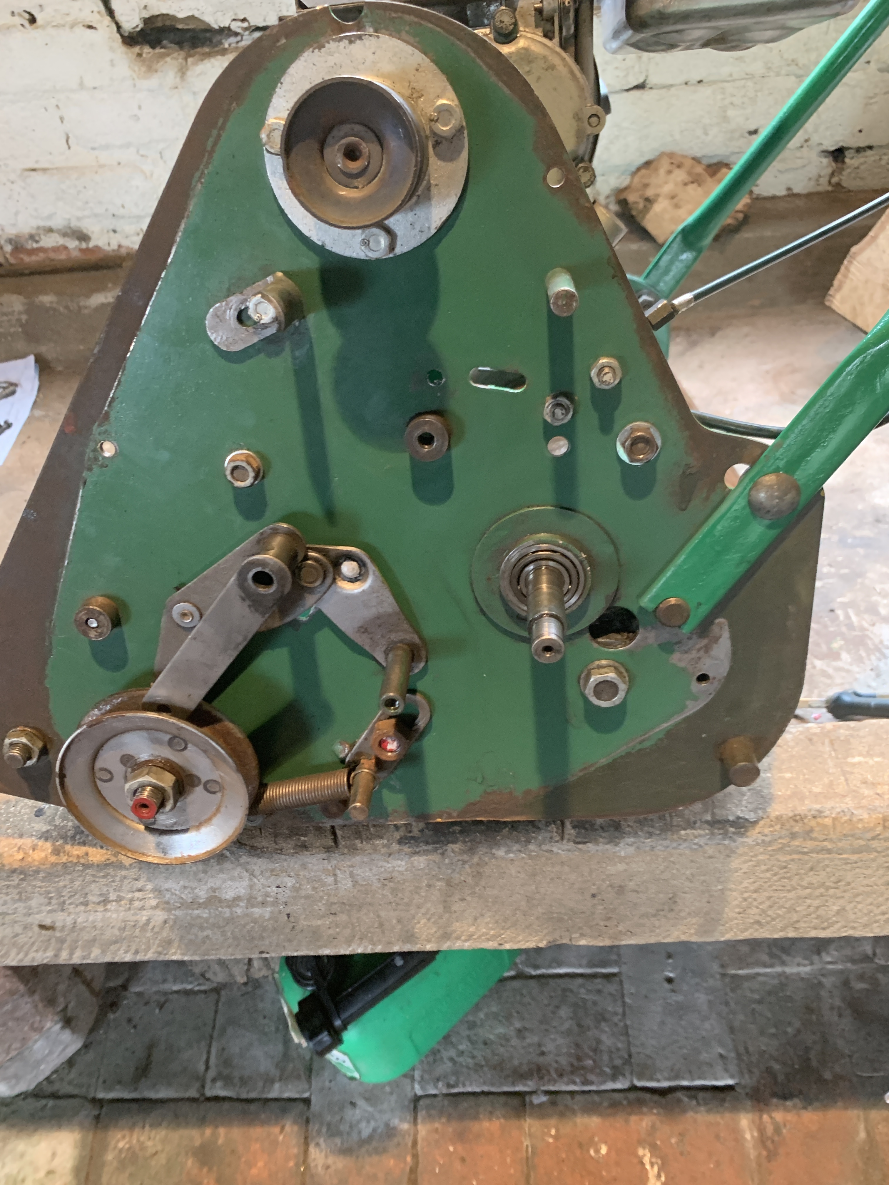
I think items 9,10 & 11 may lay at the root of the problem
So comparing the parts
So comparing the parts diagram against "as presented" it is clear that the large washer and pressure spring have become transposed at some stage in the life of this mower.
Strangely when aligned in the sequence as per the parts diagram, the large washer hits against key (4) and therefore no pressure is placed on peg plate (9).
all very odd
will examine further tomorrow, if anyone has any suggestions please shout .....
Certainly looks as though the
Certainly looks as though the order of play working inwards is the support bracket, conical spring - small end outward, large washer, withdrawal collar and pulley. The pulley freewheeled on the pinion shaft .
Even if the diagram is misleading the objective has to be to assemble it so that the withdrawal sleeve is locked to the shaft by the key but can slide towards the pulley for the pins to engage so that the pulley and pinion move as one. That’s the theory, as I see it , but you have the advantage of having the parts to play with.
Observation of the assembled
Observation of the assembled drive side. It’s years since I worked on a 14 or 18 Webb, either standard or deluxe but the drive side has many similarities with the belt driven Webb 24, a machine that I’m familiar with, having owned and used one and still service a couple.
If it follows the 24, the lower belt keeper that anchors the belt tension spring , should be below the belt . In that new configuration it looks a bit “ uncomfortable” but it allows maximum tension on the spring / belt while not tending to bow the bottom run of the belt away from the pulleys.
The top moveable keeper to the left and below the top pulley has a shape that suggests that it should push against the belt even when in drive. The correct adjustment may require that keeper to be rotated anti clockwise to roughly 2 o’clock so that with the belt clutch engaged and a bit of slack / lost movement in the cable, the keeper does NOT touch the belt ( just not) . Operating and locking the clutch lever should result in the belt touching the keeper which encourages it to lift off the top pulley and stop friction burns while emptying the box etc. The handbook for the belt driven 24 showed incorrect positioning which was never corrected and resulted in lots of premature belt wear.
Two points regarding the handlebar clutch lever. There should always be a bit of lost movement before it starts to pull the cable. As your new belt stretches and beds in that slack will be absorbed , but must be maintained especially with a new belt . I see that you have a PIX belt which is as near to the cotton covered original Dawson Speedona and should give good service. Lever. If it is worn both in its pivot and it’s trigger locking position it can result in the locked position not declutching the belt enough when you relax your hand grip. There are a couple of work arounds but if you can source a new lever it may save a bit of faff.
Thank you for very helpful
 Thank you for very helpful info.
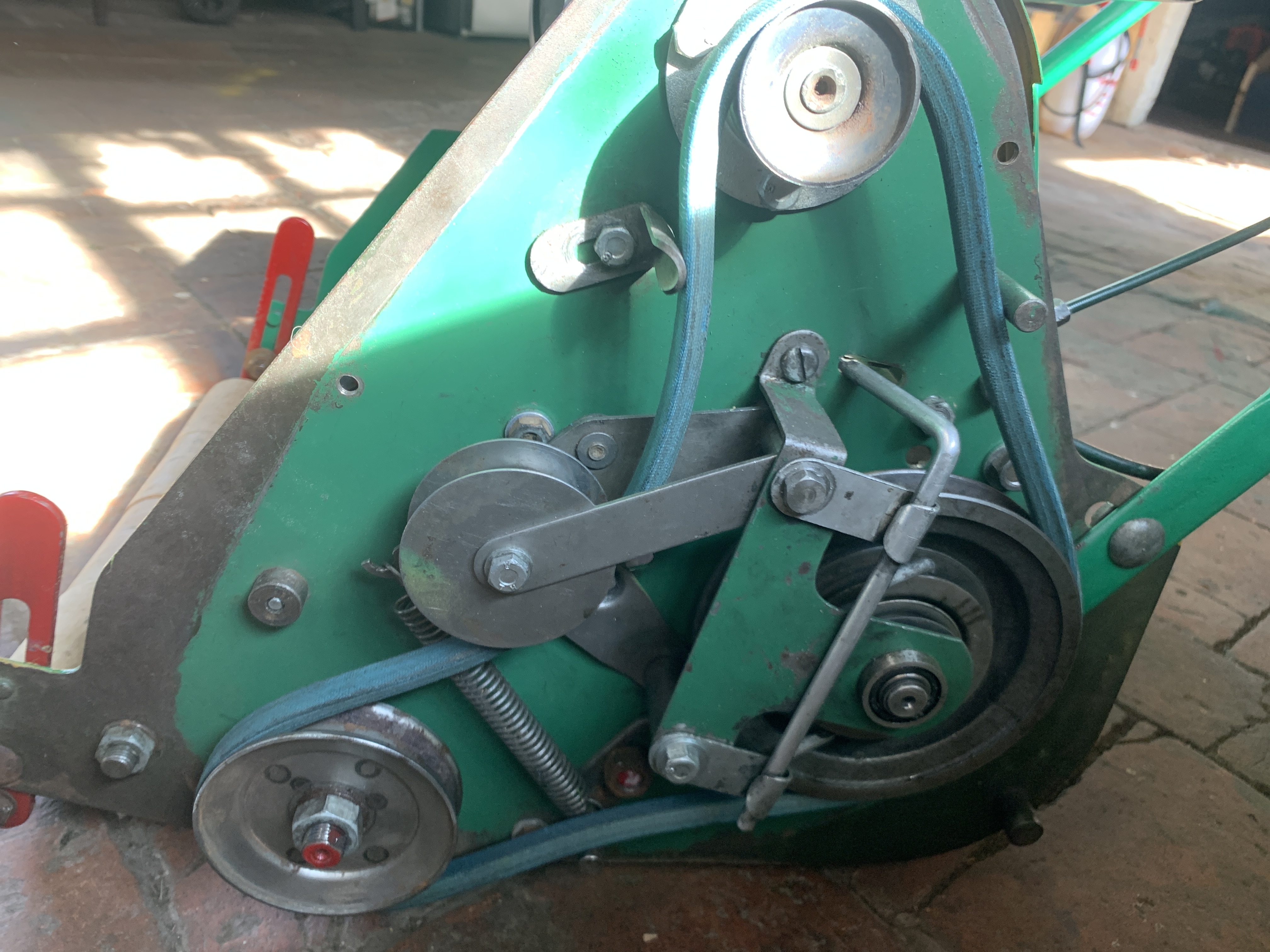
Have fabricated and fitted a roller.
have reassembled roller drive in the following order, pin wheel, spring, large washer. This is not consistent with the drawings but certainly has improved things, get drive on first release of lever then loose drive after about 10ft, pinging the lever restores drive temporarily.
should the lower belt guide be able to move or fixed ?
Slotted and on a swivel , I
Slotted and on a swivel , I believe. When the belt is in drive - under tension, it should not touch any of the pegs or adjustable keepers.
When I’m at the PC I’ll post a scan of a 24’s operator’s guide which, not exactly the same layout, will give an idea of the belt run etc.
EDIT
Apologies for delay, couldn't find the image that I was thinking of but this one shows those two critical points.
https://www.dropbox.com/s/5nmcohppor4gci2/Webb%2024%20belt%20layout0001…
This is not consistent with
This is not consistent with the drawings but certainly has improved things, get drive on first release of lever then loose drive after about 10ft, pinging the lever restores drive temporarily.
The odd thing is that the parts book shows the pin wheel assembled on the outside of the pulley in one illustration and on the inside in another. Its possible that one refers to a 14" and the other an 18" but there's nothing to draw one's attention to that.
worst of all I didn't think
Well, post some nice images from different angles and someone will tell you what you have and maybe even post an illustrated parts list.
Edit
https://www.dropbox.com/s/447cw2t4tvcmrhl/WEBB%2014%2018%20221%20232%20…