Morrison Olympic 500 Rear Roller drive problem
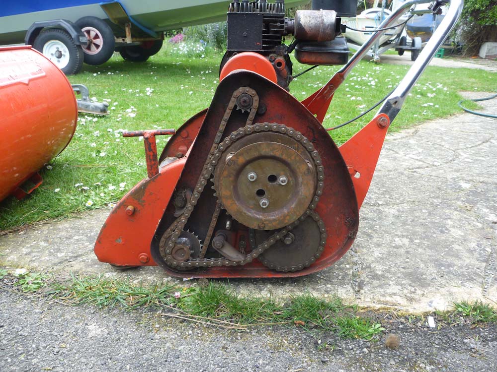
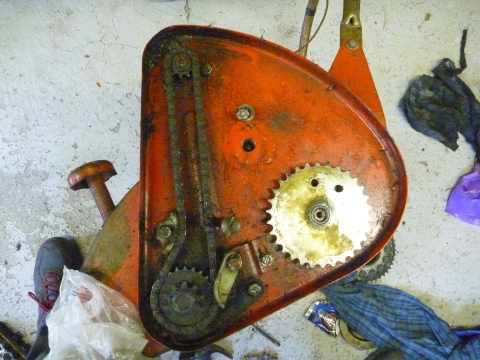
I have an old Morrison Olympic 500 cylinder mower that until today worked perfectly. The problem is that today, while mowing for the first time this year, the drive to the rear roller suddenly failed mid-cut so the engine runs, the cylinder spins, but the mower is no longer self propelled. I have checked the clutch and it is fine. The roller drive shaft appears to turn when the clutch is released but the roller itself seems to be free to spin around the shaft drive. I know Morrison is a New Zealand make but previous research showed me it is heavily based on the UK Ransomes Marquis design so I'm hopeful someone will have some advice. I've attached some photos.

")

My guess (I'm a newbie) is that there is a key and/or possibly a ratchet mechanism that connects the drive shaft to the rear roller and that this is where the problem lies. However, before I do anything I would welcome advice. Assuming I have to remove the roller, what is the correct way to do this and will I need any special tools? If I need new parts, are these likely to be available? (I do own another identical mower with a dodgy engine that I was intending to restore but could cannibalize this if necessary).
Really would appreciate any help as I would love to restore this machine to working condition and the grass is growing fast! Am loathe to take it to a repairer but if you think that's best solution, do you have any recommendations (machine is located in West Sussex)?
Thanks.
Forums


From your photo of the
From your photo of the rollers it looks as though the 'tires' have slipped along the rolls, from this I would suggest that you check that the bond between the rubber and the rollers has not failed allowing the rollers to slip inside the rubber.
That's too simple!!!
That's too simple!!!
But I see just what you mean. I wonder whether the "marine environment" apparent in the images could have anything to do with it?
Next question is could some form of adhesive be injected without dismantling? Self tappers or pop rivets might be temporarily effective but definitely be frowned upon!
Thanks both for the quick
Thanks both for the quick response and helpful advice. You are right the lawn is about 100 yards from the sea but I'm afraid it's not just a slipping set of rubber treads. Will follow your suggestion and remove the roller taking pictures as I go. It may be a while before I get to do this, however, as (unfortunately) I don't live at the place with the mower but visit when I can. If I have time, may have a go at dismantling my "spare" machine (which is in my garage) to rehearse in the meantime.
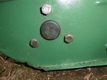
Sorry but just a few more questions: Am I right that the clutch can stay in place when I remove the roller? IE just remove the chain from the roller drive sprocket, undo the nut holding this sprocket (is this likely to be a left hand thread?), and then remove the bolts holding the bearing housing at either end? I think you then say the roller could then drop out. Have I got that right? Below are 2 photos of the LHS and RHS bearing housings which each appear to be bolted to the chassis with 2 bolts. If I remove the sprocket, then these housings am I correct that the RHS end of the roller axle/drive shaft will drop downwards and let me remove the other end (which presumably has to pass through the LHS chassis plate to where the sprocket is connected?


It's really good to know that there is hope for a happy ending to this story.
I'm guessing that the
I'm guessing that the sprocket is keyed to the shaft so the retaining bolt won't be subjected to any " undoing" torque so probably has a standard right hand thread .
With that bolt removed you just may be able to wiggle the sprocket away from the chassis and may be able to undo the bearing retaining bolts . Might not even have to break the chain. On the other hand it may be easier to clear the decks and take the clutch off followed by the sprocket. Sometimes it's more time effective to remove more than to struggle trying not to.
Been a long time since I
Been a long time since I worked on one, but yes, the Morrison is basically a Ransome clone, not surprising really, as they were built under license.
You will need to remove the clutch, you cannot the roller sprocket off until you do.
Thanks. Will follow advice
Thanks. Will follow advice and remove clutch first as suggested. It will be useful learning as well as making job easier. Will take a few photos as I go. Thanks again for the quick responses.
I have started "rehearsing"
[Sorry Wristpin - I must have accidentally uploaded my post prematurely. Here is final version].
I have started "rehearsing" what I will need to do by commencing dismantling my second Morrison (which is more conveniently in my garage at home). I need to do a more major restore on this one so the work will not be wasted.
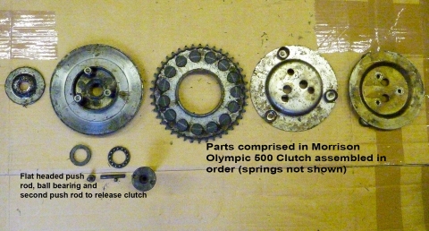
I removed the engine (as I had seen advised in another post to aid handling). This was much easier than I had anticipated. I then proceeded to remove the clutch as previously suggested so as to improve access to the roller drive sprocket. Again this was easier than I had feared. To remove the clutch plate I had to undo a bolt with a large flat head. It had 2 depressions in it which are obviously there for a special wrench (which I have seen described in other posts). However I found that it came off (LH thread) quite easily using just a pair of needle nose pliers. While doing this I noticed the clutch plate was free to move in and out by perhaps 1/8" along the shaft and was being held against the bearing. This seemed wrong but it was not clear what could be done to address this as the bolt securing it seemed reasonably tight. Any observations on this would be welcome.
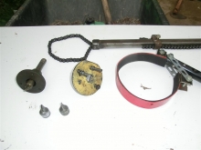
I have included some pictures below showing the various parts that make up a Morrison clutch. It appears to be quite similar to other designs but not identical.
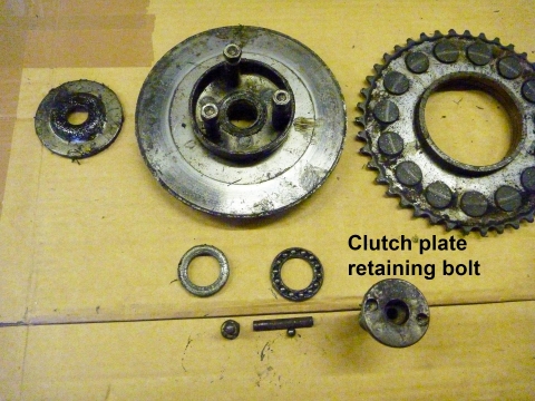
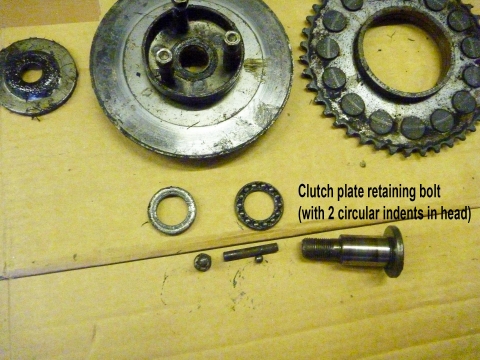
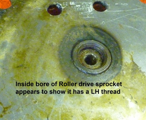
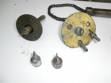
I have now reached the point where I hoped to be able to remove the rear rollers drive sprocket. The sprocket retaining nut undid easily (RH thread). However, it appears to me that the sprocket is not keyed onto the drive shaft (as Wristpin had hoped was the case) but is instead itself threaded (LH thread I think). See pictures below, one of which shows evidence of a screw thread.
I am therefore needing to find a way to hold onto the shaft while unscrewing the sprocket. To turn the sprocket I think I need to make a wrench with 2 pegs to engage with the holes in the sprocket; or possibly a chain wrench if I can get one to fit the teeth size. My next problem is working out how to hold onto the axle shaft itself.
On this machine (where the sprocket is still driving the rear rollers) the shaft can be held by jamming both rollers. However, on the machine I will eventually need to fix, the rollers are no longer attached to the drive shaft but spin freely. [Incidentally on the machine I am practising on I found that you need to jam both rollers to lock the drive shaft. If you only jam one, the other turns in reverse which suggests to me that they are (like the Ransome Marquis) inter-connected via a differential gear.]
Any advice on how to address these problems would be gratefully received!
No picture but I assume that
No picture but I assume that the bolt is through the centre of the clutch securing it to the chassis. Possibly " how it is" or may be missing a spacer or thrust washer.
See the complete post from me
See the complete post from me above. Apologies for uploading post before it was complete. Not sure how I did this.
Ah, all is revealed, as the
Ah, all is revealed, as the maiden said.
Clutch - using a thrust race whereas the Ransomes design makes do with a top-hat bush.
Roller shaft - as you say, it looks to be screwed rather than keyed to the shaft which, as you observe, can be difficult to deal with. It will be left hand thread so that it tightens in use. If it follows the Ransomes pattern the opposite end, accessed behind a rubber bung in the rh chassis side plate, will have a slot so that it may be held with a suitable tool such as a "track rod end" socket. The difficulty is that the sprocket can be very tight and the "suitable tool" difficult to keep located in the slot - even with the aid of an assistant. I've done (and still do) a fair few Marquises and working single handed, have made a fixture that bolts to the side plate using the bearing carrier screws (3 on a Marquis) with a welded "male" that is held in engagement with the slot.. Even then it can be a struggle and I would suggest warming up the centre of the sprocket to cause a bit of differential expansion to ease things. Doesn't have to to be red hot, just good and.....! It looks as though in the dim distant past Ransomes may have offered a tool to hold the slotted shaft as in the tools section of an old operator's manual is "LCG427, Key for Landroll"; but in forty years of playing with mowers I've never seen one.
Turning the sprocket. As you have the luxury of the two holes, a substantial piece of flat bar a couple of feet long, drilled to take two decent sized bolts with nuts will make a suitable one off peg spanner. You could use a bit of tube instead of bar stock or, I suppose at a pinch, a bit of 2" x 2" timber. I might be tempted to drill another hole directly opposite and across the centre from one of the existing ones to get a more symmetrical mechanical advantage - if that makes sense? Again with the Ransomes comparison, no holes on a Marquis so a chain wrench or giant peg spanner to engage the sprocket teeth, it is.
Jamming the rear roller. As you correctly observe, with the diff correctly secured to the shaft it is necessary to restrain both roller sections but with the "no drive" situation on the sick machine that option is not open to you.
I will add some pics of my various "weapons" later.
Thanks Wristpin. Will
Thanks Wristpin. Will investigate use of chain wrench and/or making tool.
I was trying to understand your advice on the possibility of holding onto the drive axle from the RH (non-drive) end. To do this presumably I would need to remove the RH side of the chassis by undoing the various bolts that attach it? Or have I misunderstood?
I have contacted Morrison (now Masport) in New Zealand to see if they have any Service Manuals for this model. So far all they could find was a copy of the Operating Manual which though interesting obviously does not provide engineering detail. If the Club would like a copy I can upload it.
If its similar to a Marquis
If its similar to a Marquis you just remove the rubber plug in the rh chassisplate and insert the holding tool through the hole. I'm a bit pushed for time today but I will try to upload some pics of a Marquis that I happen have on the bench.
EDIT. Just found a couple of "stock" images ."Third hand" shaft holding tool inserted into slotted end of shaft and bolted through the chassis side plate into the bearing carrier.
l.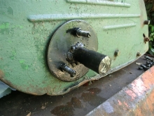
one version of a sprocket turning tool
 .
.

Good idea re locking the
Strange case of the missing text!!
I posted this to say that there is no bung on the right side chassis plate and I see that has now been confirmed, hopefully the shaft can be locked up using the flats that have been located.
Only problem with removing
Only problem with removing the bung on the dead side of the Morrison rear roller, there isn't one ;-)
I seem to 'think' I remember that there are two flats on the roller shaft for a spanner to jam the shaft, but it has been more than twenty years since I last saw a Morrison and then it was a triple.
Somewhere I actually have the official Ransome Marquis roller locking tool, again I haven't used it for years.
Yes, as one of the pictures
Yes, as one of the pictures in my first post shows the Morrison RHS panel has no rubber bung. However on closer inspection I found Hortimech is right. There is a flat on the shaft at the RHS which a suitable spanner might hold. Am currently in process of making a tool to hold onto the sprocket end but will turn my attention to finding a suitable spanner for the other end tomorrow.
Thanks again all.
Problem solved then. You just
Problem solved then. You just need a spanner long enough to locate against something solid ( the sole plate / bottom block?) so that you can apply the necessary force to the sprocket.
Somewhere I actually have the
Somewhere I actually have the official Ransomes Marquis roller locking tool, again I haven't used it for years
Any chance of an image. I'm guessing like an oversized Allen key with a flat end to engage the slot.
OK. So I have established
OK. So I have established the spanner needed to hold the axle is 3/4" (~19mm) which unfortunately is the one size my metric set misses. Have ordered one on eBay so work will stop for a while until it arrives. The gap width the spanner must slide down to get to the axle is just 6mm so hopefully the one I've ordered will not be too thick. My sprocket tool is now nearly ready and (if it works!) I will post a photo of it plus what it reveals when the roller is removed.
I would to actually have to
I would to actually have to find it first ;-)
From memory, it isn't as you described, It is a more like a round bar, turned down, then reduced again and finally shaped to go into the end of the roller shaft. You secured it with a large pair of Stilsons whilst trying to undo the sprocket. The other thing was, it general didn't work and you ended up using the Stilsons on the rolloer shaft instead.
OK. Time for an update.
OK. Time for an update. After a couple of false starts, I successfully acquired an 11/16" spanner and painstakingly ground it down until it would just fit into the "flat" cut into the RHS axle. It turns out it wasn't 3/4" - teaches me to measure it more carefully next time! I made myself a sprocket wrench building on the picture Wristpin posted so that 2 bolts engaged with the teeth on either side and also a crosspiece bolted into the 2 holes Morrison had kindly drilled in face of the sprocket (all made out of some scrap shelving supports in an attempt to save buying a steel bar). It was extremely tight so I applied heat, let it soak with penetrating oil and placed the machine upside down so I could press down with my lever. I also jammed the roller as well as holding the RHS axle with the spanner as a sort of belt and braces approach. I was apprehensive but it worked - see pictures. NB The photo showing my home-made wrench was not taken with the mower in the (upside down) position I used to apply maximum force.


So this is my "spare machine"; i.e. the one I'm practising on. The machine with the "disengaged roller" is still to be tackled but with the help from this Forum at least I now know how to remove the roller and have the tools to do it. I seem to have 2 options. The one I favour is to take this roller down to Sussex and exchange it for the faulty one in the machine down there. I can then bring the faulty one back and refurbish it at my leisure and leave a (hopefully) working machine to cut the grass. I favour this option as I am not sure what I will find inside the faulty roller or how difficult the problem will be to fix. My expectation is that the keying arrangement that locks the axle into the central cog that drives the 2 differential gears has somehow failed. Wristpin agreed this was likely and I am thinking I may need to source a new key/pin or something that has fallen out? I have no idea how difficult that will be.
I also have to learn how to get inside the roller now I have removed it. In the photo above I note there is a circlip which I presumably remove to release the bearing? There also seem to be a whole set of shims too. Any advice on tackling this next phase would definitely be appreciated. In the mean time, many thanks for the help thus far which gave me the confidence to tackle this.
All good news and the roller
All good news and the roller swap sounds like a good plan - unless of course they are of different generations and dimensions. Lever or pull off the bearing at either end . If levering try not to damage the bearing seals . Then remove the Circlip and shims. The shims are probably a " use as required " item to minimise the clearance between the roller sections or end float while still allowing them to rotate independently. The roller section should then pull off.
Anything that has sheared in the diff department is probably standard hardware and if it's a broken weld electric glue should fix it.
Good that you are making
Good that you are making progress and it sounds like a good plan to switch the rollers (assuming they are both the same) I noticed that the second machine has no rubbers on the rollers, I wonder if this is original or have they been removed at some point in the machines life?
An interesting form of lifting sling there! A case of needs must I guess.
OK, so I'm now down in Sussex
OK, so I'm now down in Sussex attempting to apply all my learning to the machine with the roller problem. I first attempted to remove the engine which had proved straightforward on the machine at home. However, having removed the 4 mounting bolts, the engine refused to slide away from the centrifugal clutch. Previously the internal part of the clutch had slid out effortlessly. Loosening the grub screw on the shaft made no difference. There seemed to be about 1/4" or so of movement and then something was holding the shaft back. Here is a photo which shows some bolts throught the engine-side face of the clutch which I don't remember seeing on the other mower.

Removing the grubscrew that locates through the boss of the engine-side clutch piece and keys into the engine drive shaft did permit the engine to slide away about 1/4" to 1/2" but no more. When this happened it was the engine drive shaft sliding inside boss of the clutch. The inner rotating part of the centrifugal clutch would not disengage axially from the outer part. I should say the inner section was quite free to rotate independently of the outer (i.e. it had disengaged as expected given the engine was not running).
Any thoughts on this appreciated. I have moved ahead with the plan to remove the roller but am having to do it with the engine in situ which is not ideal.
My second question concerns the drive chain between the centrifugal clutch sprocket and the cylinder sprocket. To an ex-motorcyclist this seemed very slack. See photo.

All chains were very dry. So I will oil properly before reassembly.
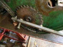
Lastly, I thought you should see the state of the cylinder sprocket which shows signs of a major welded repair. Not sure it's a problem but any views welcome.


I am leaving the roller drive socket to soak in penetrating oil overnight before I attempt to unscrew it tomorrow. Wish me luck!
Oh dear, we used to have a
Oh dear, we used to have a technical term for a sprocket like that, but I cannot repeat it here ;-)
You need to replace it and you may have to fabricate it yourself, I also think you should replace the chain. Your local bearing supplier should be able to to supply sprockets and chain, try searching yellow pages etc.
Thanks, Hortimech. I did not
Thanks, Hortimech. I did not have the time down in Sussex to follow your advice but my plan is to fit the sprocket from my "spare" machine (picture below) and possibly its chain on my next visit. Do you have any recommendation for firms that would fabricate a new sprocket? I live in Cheltenham and this appears to be my local bearing supplier http://maydayseals.co.uk/ .

The good news is that I did once again manage to remove the roller sprocket with the tool I made earlier and the roller itself. Also, the replacement roller (though looking a little different due to lack of rubber tyre) did fit. And having replaced everything, adjusted the roller clutch, and allowed the engine oil that had filled the combustion chamber to seep back to the sump once the machine was the right way up again, the mower started and everything worked! The chain was a bit noisy even after I took up as much slack up as poss with the adjuster. But hopefully I will be able to address that at a future visit.
One new problem arose. There seems to be a slight leak from the petrol tank which (I think) comes from a seam where the filler nozzle joins the tank. My plan is to seal with some sort of epoxy tank repairer.
Having returned home with the faulty roller, I used a 3-leg puller to remove the 2 end bearings (I'm glad to say without causing them damage). I then removed the circlips and shims and eased the 2 halves of the roller apart. Below is a picture of what I found.

The pin that locks the differential gear carrier to the shaft has clearly slid out. So no need for any new bits. I assume that this pin just needs to be relocated? Or should I take it out and "spread it to make a tighter fit? Also is there any other work I should do while the differential is exposed?
Many thanks to everyone who has helped me with this repair so far.
As they are spring steel I
As they are spring steel I think that spreading may result in a broken pin. Doesn't look as though the layout lends itself to a wire tie through the pin but a piece of gas welding rod through the pin with a sharp L bend on each end would retain it. Otherwise clean it up and Loctite it or even go out shopping for a new pin. At a pinch you could use a bolt and nylok nut.
As far as "anything else" goes you could clean the old grease out and replace it with fresh but it doesn't look that bad.
Thanks Wristpin. I have now
Thanks Wristpin. I have now extracted the roll pin. As you can see it was broken so I have ordered a replacement.

Not quite sure why it failed but hopefully the replacement will see me out.
Do you have any thoughts on why I was unable to separate the engine plus inner part of centrifugal clutch from the outer (see my post at #25)? Is it just a question of applying more force? I don't need to do so right now as I worked on the mower with the engine attached although it was not ideal. I'm just thinking there may come a time when I will need to tackle this. The same joint on my "spare" machine came apart without any problem at all.
If it follows the Ransomes
If it follows the Ransomes design there will be a self aligning ball bearing in the clutch back plate which is attached to the engine. The end of the top shaft that carries the clutch drum is supported in that bearing. Ransomes experience is that sometimes the shaft can be a very tight fit in the bearings , sometimes to the extent that separating the engine pulls the bearing itself out of the back plate. If that happens you can use a conventional legged puller to remove it from the shaft when I would suggest that you use fine emery cloth tape to reduce the end of the shaft to a more comfortable sliding fit.
Thanks Wristpin. I have now
Thanks Wristpin. I have now examined the centrifugal clutch of my "spare" machine (which separated easily) and what you suggest makes sense. See pictures below.


Now I understand this, I'll feel a bit more confident to apply a bit more force next time I have to separate engine from mower.
Hi
Hi
I would like a copy of this manual please
regards Dave
I'm afraid I don't possess a
I'm afraid I don't possess a workshop manual for the Morrison. All my work was informed by advice from this Forum. I did find a user manual online and will try to upload this.
OK. Hopefully you can access them from this dropbox link: https://www.dropbox.com/sh/g11du81nfj9nhmq/AAAaGU8eW70FndeULGsMuuMqa?dl…;
Thank you so much for this, i
Thank you so much for this, i really do appreciate this .
kind regards Dave

I was contacted by a non
I was contacted by a non-member based in Australia who has a number of Morrison mowers. They offered some advice that might be useful although they didn't want to join the forum for a single post. There comment as follows:
Nylon drive cogs in the middle of the rear drums wear and this either stops propulsion or affects the turning in one direction.
Advisable to replace the four cogs. However, the larger cog often wears before the smaller cog.
Replacement parts can be obtained from here :
Assuming that the sprocket is
Assuming that the sprocket is driving the shaft I think that your "guess" is correct. I've been into plenty of Marquises but never a Morrison but assuming that it shares the Ransomes ratchet mechanism your problem may be no more serious than a sheared or loose cotter or roll pin securing the ratchet mechanism to the centre of the shaft.
As far as dismantling goes it looks as though you are in luck in that it appears that the sprocket is bolted (and keyed) to the shaft rather than screwed on as per the Marquis. - they could be a pig to get undone. My guess is that with the sprocket removed the hex head screws holding the shaft bearing will be revealed with corresponding ones on the RH side of the chassis . Remove those and the roller should drop out. Looks as though the RH roller will be easier to remove (not sure about that casing at the LH end) and hopefully with that off the ratchet hub will be exposed and the cause of your problem revealed. I don't know why, but a little voice is saying that Morrisons may have welded the hub to the shaft so maybe a failed weld rather than a pin. When you get in there lets have some pics of the crime scene!