First ever Restoration - Suffolk Super Colt - Lots of questions!
Hello all, I've been browsing the site more and more recently - mainly from search results while googling for information. After giving up cycling recently due to health problems i needed something to help pass the time and something to fettle with! I've always carried out servicing and repairs on my own cars and bikes, learning along the way and reading up about things i didn't know how to do, and like to think I’m mechanically competent.
There has always been something about engines that has intrigued me, and so i decided to see if I could strip down and refurbish a lawnmower. One came up nearby on the bay, a 'Suffolk Colt' which was advertised as spares / repairs due to 'No Spark - suspected coil'. I figured it was worth a punt and would be a good learning experience even if i can't manage to get it running. Looking online, Colt's didn't seem to quite match the look of my mower, which led me to discover it's actually a 'Super Colt'.
What started off as a simple 'Let's find out why it's not sparking' quickly resulted into a complete strip down of the entire mower and lastly the engine!! Taking plenty of pictures along the way, and bagging up nuts and bolts with labels so as not to forget what went where, I've now stripped the entire thing down so that I'm left with the engine block, and an exhaust that is well and truly welded to the block - thankfully it doesn't appear damaged, just rusty, so It can stay where it is (frustratingly for my OCD).
I'm going to test the waters here to make sure I can upload pictures properly, and once I can, I'll post up a few pictures I've taken during the strip down. I've come across quite a few things I’d really appreciate some advice with so anyone interested in looking/reading can hopefully help me out - which I’m hoping will help others out in future who are thinking of tackling the same sort of project.
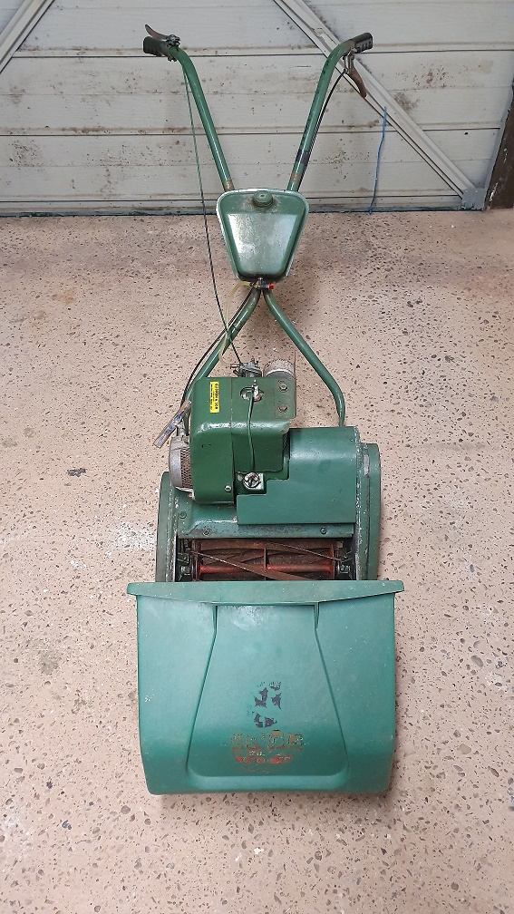
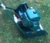
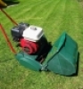
Here is a Picture of the mower after collecting it
Forums

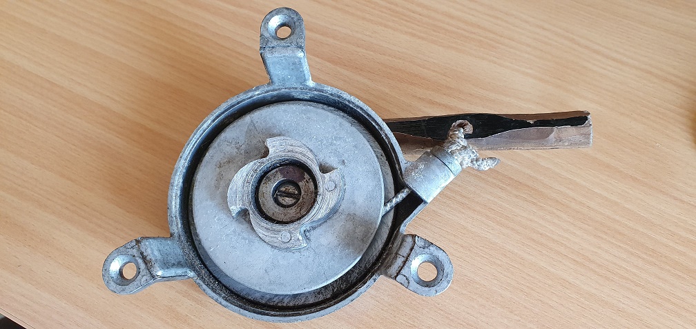
Movement as indicated by your
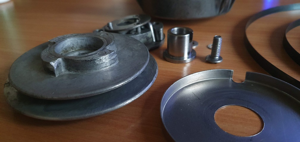
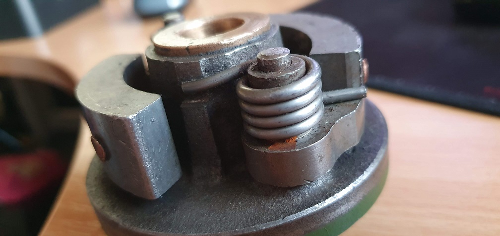
Movement as indicated by your arrows is probably that provided by self aligning function of the spherical bearing in the side plate. If, when the drum is supported by the clutch spigot bearing, you can lift the sprocket up and down any appreciable amount you may need to consider replacing the spherical bush.
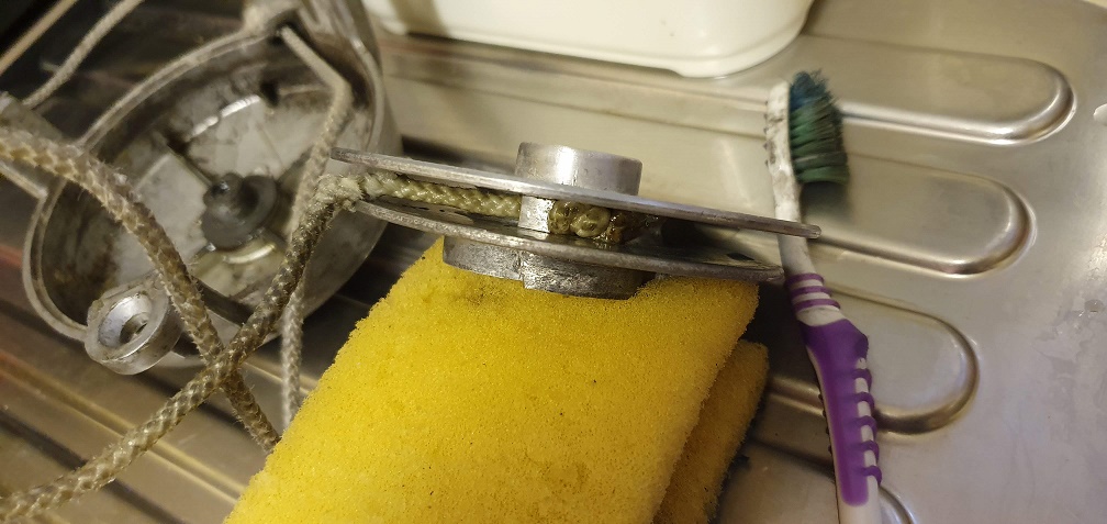
Holding the drum. Grips or stillsons around the smaller diameter boss . Make sure that you replace the hard steel thrust washers - one each side of the bush - different sizes.
I have seen the felt pads
I have seen the felt pads available but decided to make them.
I've had quite a lot of slop on later model clutch housings also and its not been an once assembled, but would heed the advice as mine were a lot younger!
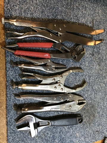
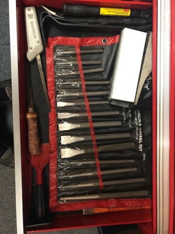
Re holding one thing while turning another, more toys... last resort always mole type grips but the first clutch holding tool pictured left has been excellent
Impressed with your deep dive into this jobbie, interesting reading!
Thanks for the advice - I'll
Thanks for the advice - I'll see what it's like once I can offer the engine and clutch shoes up to drum again, which feels like a long way off at the moment! If i can get the nut off in the meantime I might dismantle that section just to check for any obvious damage/missing parts/wear.
Glad someone is finding it interesting reading :) I'm enjoying learning and absorbing as much information as I can from the wealth of experience on this forum. I've read through all of the technical threads on here that sounded either relevant or interesting and that alone was really worthwhile.
A few more updates...
On the subject of cylinder bearings and housings, I've had the vinegar out soaking a few rusty parts and cleaning them up. Height adjustment springs before and after
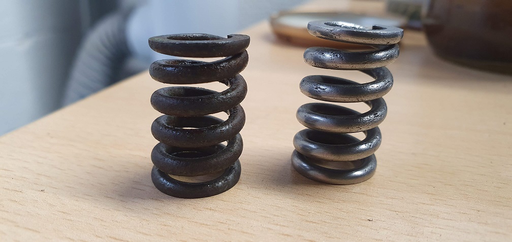
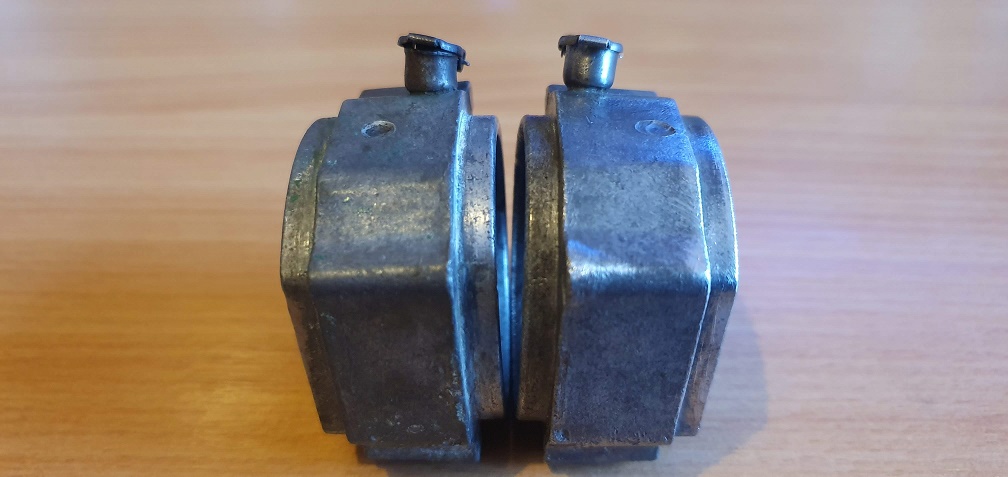
The oilers on top of the bearing blocks were not closing properly, so after cleaning them through and adjusting them carefully, they now spring shut and sit nice and level to keep debris out (which is why they were packed solid full of rubbish and blocked originally). Only a small thing but might as well put it right
Original on left, cleaned and adjusted on right
Only a small thing but might
Only a small thing but might as well put it right
It’s the small things, visible or hidden, that are the makings of a nice restoration.
Thanks Angus, I want this
Thanks Angus, I want this restoration to be the best that I can make it with the tools and skills that I currently have.
The cylinder bearing cone that should have been free to move but was rusted in place needed a good clean up. It's certainly not going to be silky smooth but I don't think it warrants spending more than the mower cost me on a replacement!
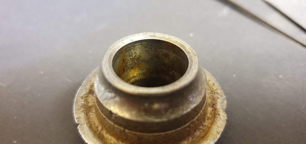
So after some cleaning up inside the cone and around the face, as well as the tin hats on both ends, oilers cleaned and caps adjusted, springs de-rusted, I now have all the bearing parts cleaned/replaced and ready for when the time comes to reassemble everything
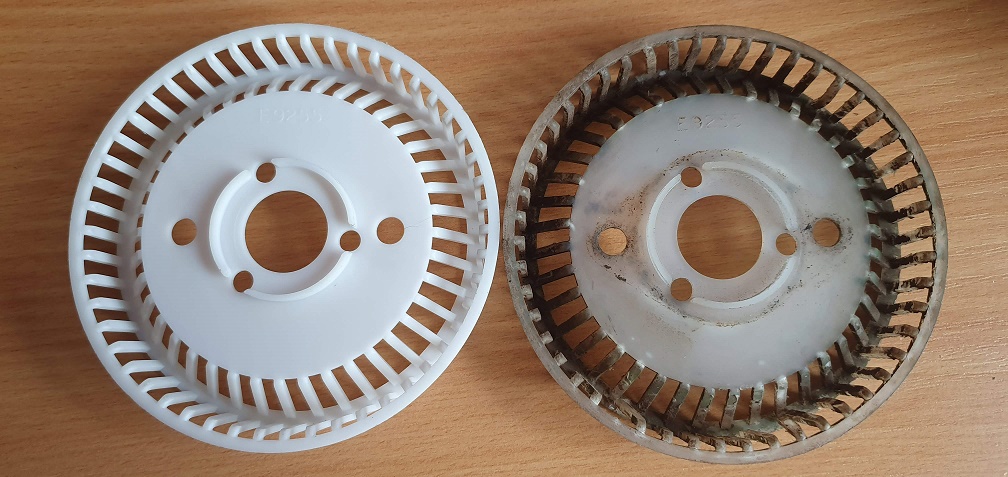
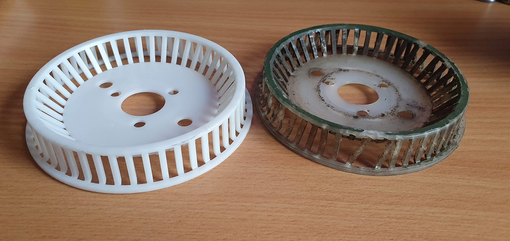
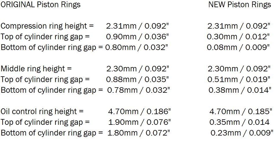
In other news, I've sources a couple of replacement parts. The first is part E9255 which is the recoil starter plastic grass shield - the original has several broken 'legs'
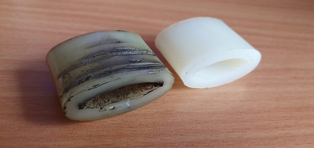
The second is part L7063 - the nylon slipper for the chain adjuster - the original had very deep score marks nearly all the way through the nylon
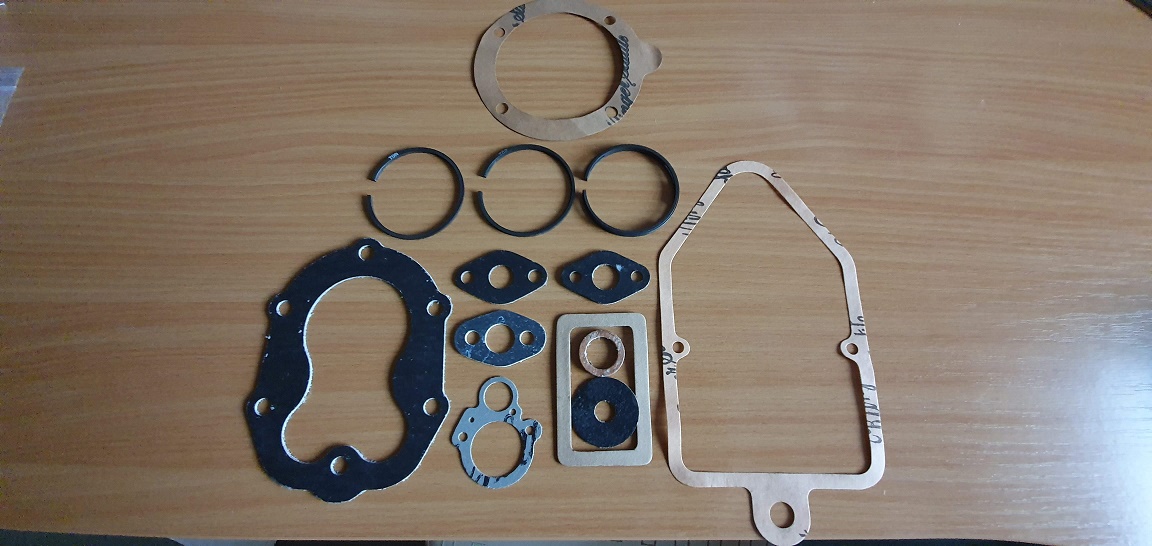
Also a complete set of gaskets courtesy of Jon at The Mower Centre (Great service by the way) as well as a new set of standard sized piston rings
I was shocked at how much harder the new rings were to fit inside the bore compared with the old ones. I re-measured the old ring gaps again as I wasn't 100% confident I had the measurements right having not done it before. Re-checked them, and then took my measurements in the same locations with the new rings. Results below
The ring end gaps have reduced by a fair amount - do these figures look more acceptable in terms of providing compression and oil control?
Your plastic debris screen is
Your plastic debris screen is wrong for an engine with the alloy starter shown in one of your earlier posts which has its own expanded metal shield. Alternatively it is correct for the later plastic bodied starter which would require a different starter cup screwed to the flywheel.
You are probably better off using the alloy starter with a new rope and handle but it’s possible that to accommodate the thickness of the plastic screen a metal spacer washer has been omitted from behind the starter pawl assembly, so if you dispense with it you may have to find a suitable spacer. Alternatively you could trim down your old plastic screen so that it is visually correct while still acting as a spacer. The metal starter is a better unit giving positive engagement whereas the later plastic one was not known for its reliability.
Well that just goes to show
Well that just goes to show that even with the owners / operating manual with exploded diagrams, you still need 'The Knowledge' to get things right on these mowers! Thanks for clarifying that Angus.
So the metal screen that I have should actually be in place of that plastic screen, seeing as I have the earlier alloy starter. Someone really wanted to keep the debris out!
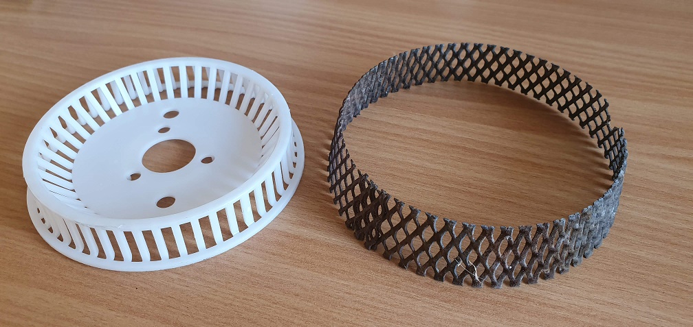
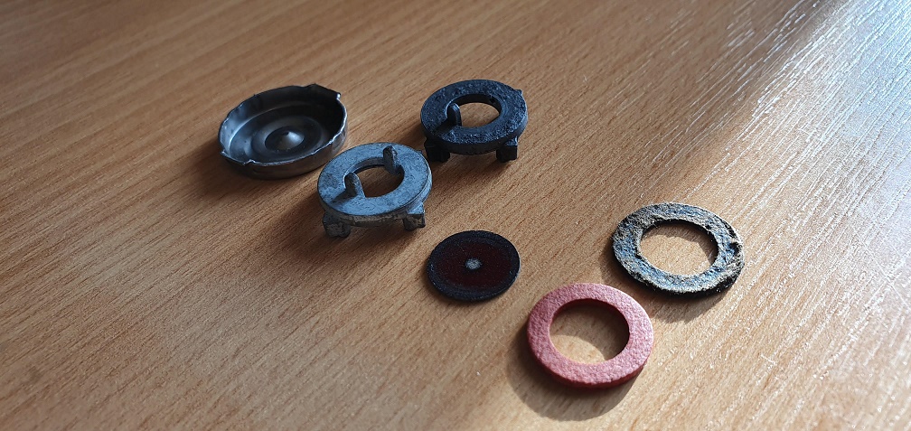
I think I do actually have the spacer you refer to, as this is what was fitted before I dismantled things - the spacer on the right, is that what you were referring to?
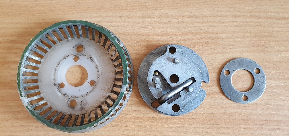
I'll replace the handle and rope with new ones, and see if I can clean up the alloy body a bit. It turns ok, but feels a bit sticky/gritty, so I'll open it up and give it all a good clean. Does that look like everything that should be there?
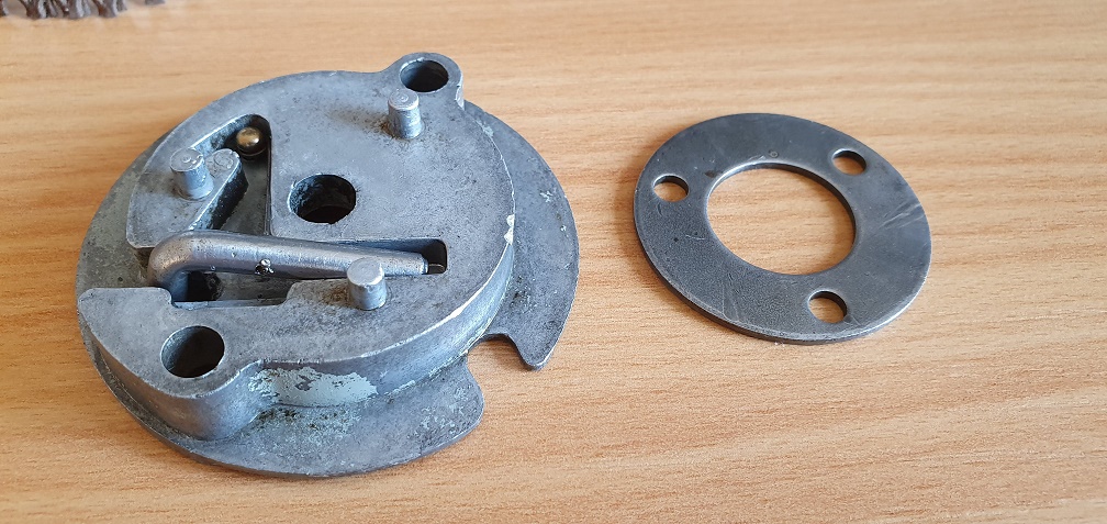
Yes, that’s the spacer, so
Yes, that’s the spacer, so you should be able to discard the plastic screen will no ill effect. What I can’t see is the little hairpin spring that controls the movement of the pawl. It needs to be there for the starter to operate properly.
Ah yes, present and accounted
Ah yes, present and accounted for ;)
That’s the one!
That’s the one!
Right so having never taken a
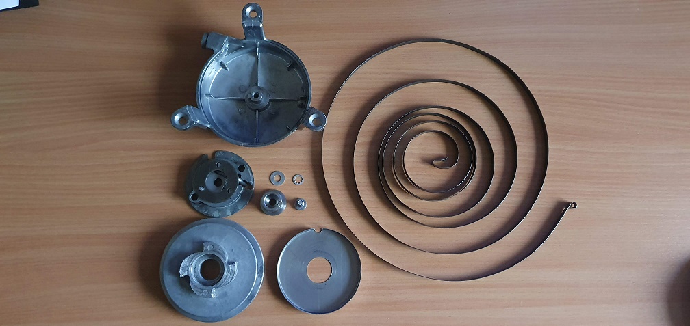
Right, so having never taken a recoil starter mechanism apart before, let's see what's involved...
I have a feeling the spring might be 'interesting' to coil back up :) Time for a good clean up
All cleaned up ready for reassembly when I get my new rope and handle
While waiting for my new
While waiting for my new starter handle and rope to arrive, I found a very useful post by Wristpin with a detailed explanation of how to rewind the rope and spring on these starters - https://www.oldlawnmowerclub.co.uk/forum/atco-4-stroke-starter-cord-set so I'll be referring to that when the time comes! Would something like 3 in 1 oil be a good choice for lubricating the recoil spring, rather than a grease, in order to keep the movement smooth and not get gummed up in future?
In other news, I've sourced a new con rod and a much better condition used crankshaft. The original con rod big end bearing surfaces had a very deep score mark right down the centre, almost like 2 halves had been butted together badly
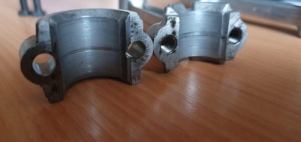
Old and new bearing cap comparison
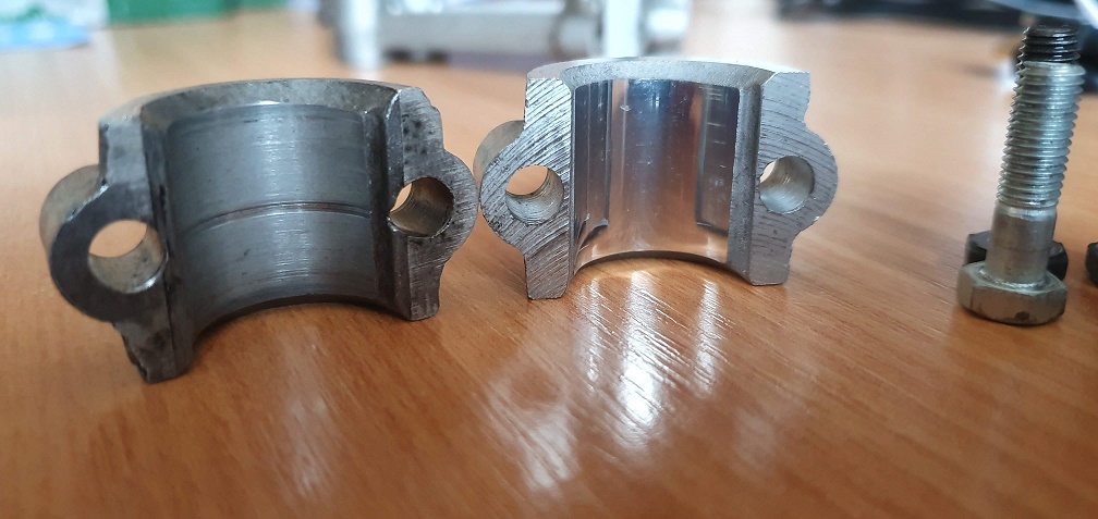
The new bearing surfaces have a mirror like finish to them, and the cap uses shorter metric 10mm bolts
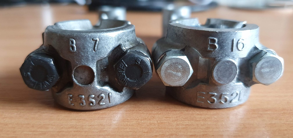
Also, the new bearing cap has an 'Outie' instead of an 'Innie' for some reason :)
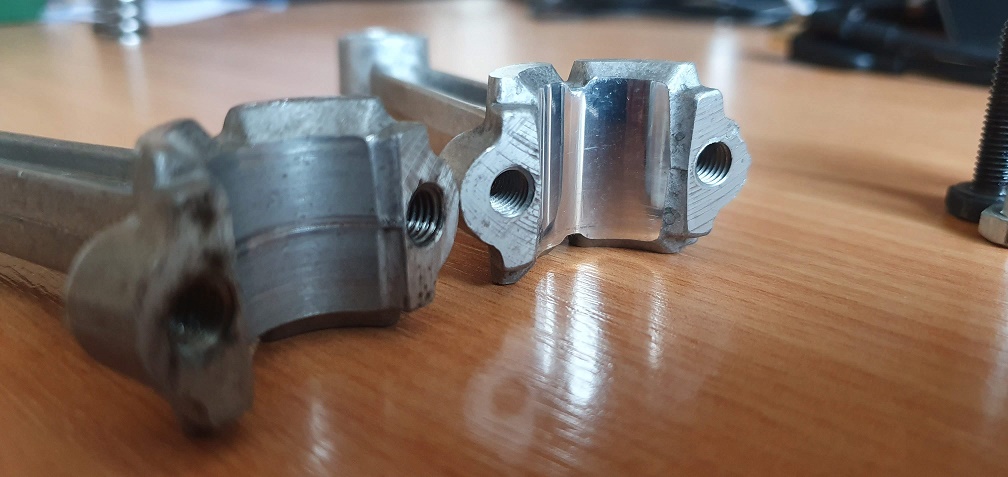
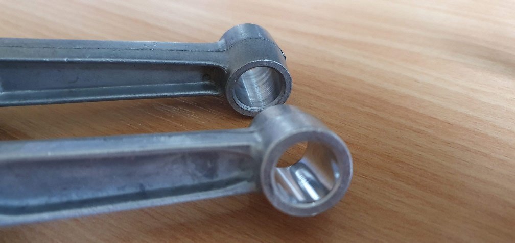
Mirror finish on small end bearing surface
New oil flicker
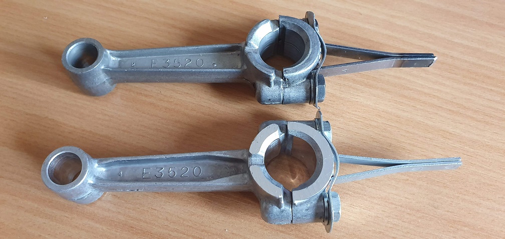
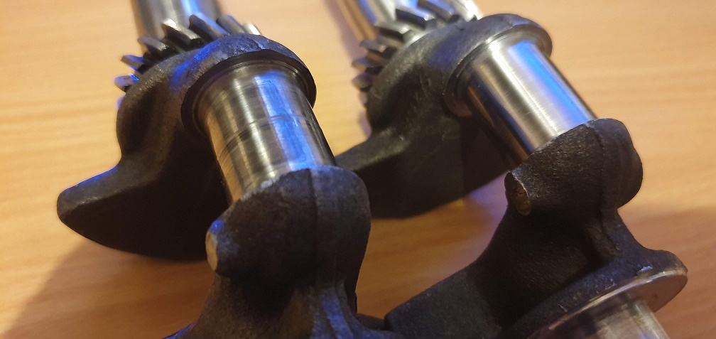
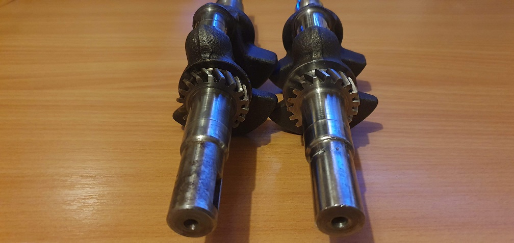
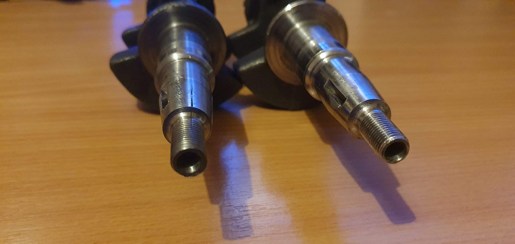
And the crankshaft comparison. A few things wrong with my original crank - the stress fracture/s at either end as well as the large score mark running around the centre journal - correlating to the score on the old big end bearing
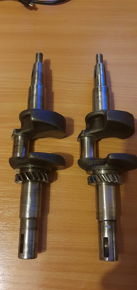
These bearing surfaces are much better
QUESTIONS - should the journal surface be polished to a near mirror finish to match the new con rod? I've seen journal polishing on car crankshaft journals before but don't know if the same principal applies here? If not, should the new con rod bearing surfaces be 'honed' to take away the mirror finish a bit? Not sure if it's similar to honing the cylinder bore to remove the glaze, and enable a film of oil to stay on the bearing surfaces?
I’d leave everything as it is
I’d leave everything as it is , but just check the clearance between the dipper and the sump, it looks longer than the original but it may just be the camera angle.
That new con-rod looks like
That new con-rod looks like it is out of an Aluminium engine, the later 98cc version, that is when the engine threads changed to metric.
That new con-rod looks like
That new con-rod looks like it is out of an Aluminium engine, the later 98cc version, that is when the engine threads changed to metric.
I was concerned about that but the part numbers are correct for the cast iron machines - perhaps very late production ?
The oil flicker is the same
The oil flicker is the same if not a fraction shorter than the original, so it's just the angle of the photo making the new one look longer.
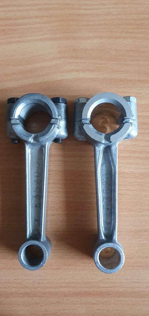
Regarding the con rod, it was advertised as being for the 75CC Sufoolk engine, with a Central Spares part number of CS10818. The rod has part number E3520 on it, which matches my original one, and going by the parts list on the operating manual, is for the 75G14 engine (E3519 is for the entire con rod assembly by the looks of it).
The parts manual for the 98G14 engine lists the con rod as part number E8214, although I can't find any pictures online so far of a suffolk con rod with this or similar number on.
Perhaps as it is (I assume) a pattern part and made much more recent that the original, it is using the metric bolts like the later 98cc aluminium engines did?
Noticed a couple of small
Noticed a couple of small casting marks on the con rod, so I will smooth these off to avoid them finding their way into the oil in the future
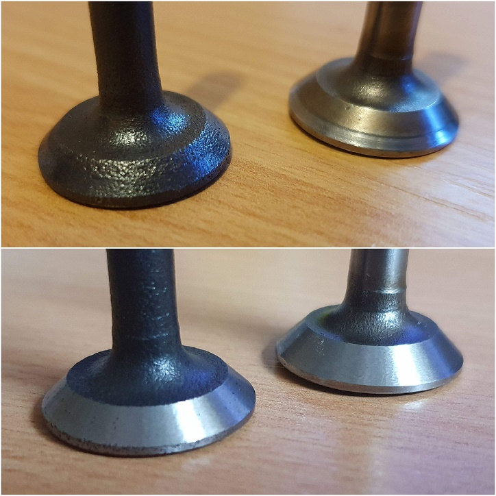
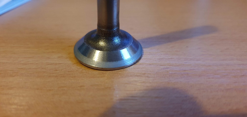
Going back to the valves for the time being. Another club member helped me out with refacing the valves at the correct 45 degree angle. Previously, the inlet valve wasn't bad, but the exhaust valve had a lot of corrosion on it, so I was unsure how that one would clean up. Remarkably well was the answer! Obviously given the extent of corrosion on the exhaust valve, getting rid of all the pitting would be impossible without removing nearly all of the metal and leaving practically no margin, but both valves should work much better now
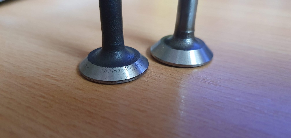
A before and after comparison of the worst side
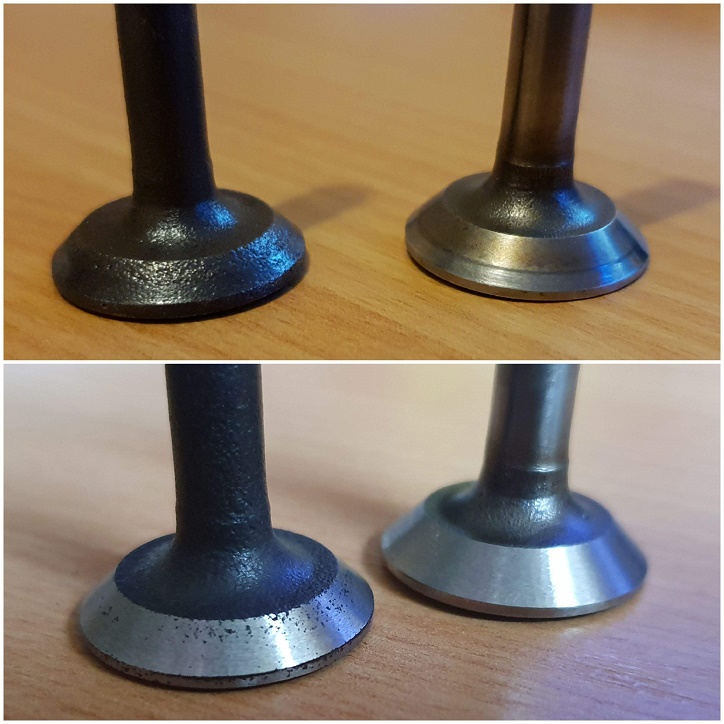
and better side!
Great result. Next will be lapping them in with the valve seats. The seats don't look too bad and have cleaned up fairly well in terms of removing carbon deposits, but I suspect the exhaust valve seat will no doubt have some pitting.
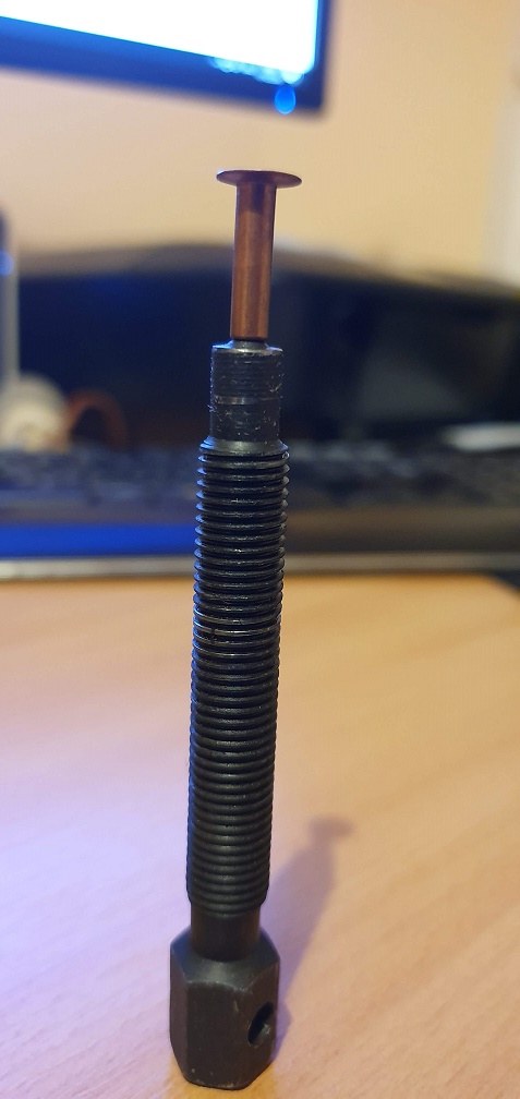
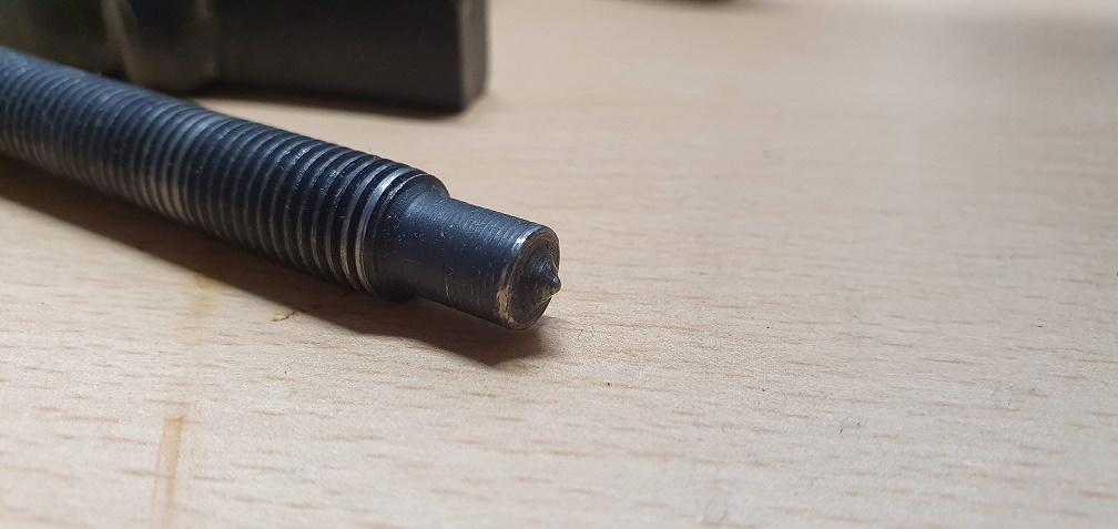
I've been trying to source
I've been trying to source the correct diameter silver steel rod, but finding the correct Imperial size is difficult, and it looks like it may have to be a metric size instead. The nearest imperial size I could find to my measured diameter was 7/32" so I got hold of a short length of that off the bay, however it is just slightly loose in the dowel holes in the sump. Not sure if these holes are tapered or not though.
7/32" is approx 5.556mm but i'm struggling to obtain an accurate diameter of the holes as my digital verniers seem to be playing up recently, giving very inconsistent results even with a new battery, so they may be past their best.
The nearest approximation of size I can guestimate using the verniers and trying to find something around the garage that fits in the holes to measure (no drill bits I have tried are the correct diameter), seems to be about 5.75mm or 0.226", so I'm on the look out for metric steel rod available in this size now. Bit of a faff for such a little thing but I want it to fit snug. I thought Suffolk would have used a common imperial size at the time!
I doubt if they are tapered
I doubt if they are tapered but , I suppose could fractionally stepped to be tight in the block and just snug in the sump pan. Alternatively the holes in the sump pan may be a gnats over size to allow for easier assembly . However , according to my vernier they are 7/32 , 5.68mm or thereabouts so why not get a bit of 6mm and in the absence of a lathe, stick it in the drill and reduce it with emery cloth until a tight fit in the block and a slightly easier one in the sump pan.
( Loctite May be your friend!!)
Thanks Angus, I've literally
Thanks Angus, I've literally just found and ordered some 5.75mm x 15.8mm steel dowel pins from the far east - on a slow boat with approx 50 day delivery, so I've got time to get a few other things sorted while I wait!! If I get to the reassembly stage and get impatient then I will do as you suggest with some 6mm and emery cloth as (sadly) no lathe.
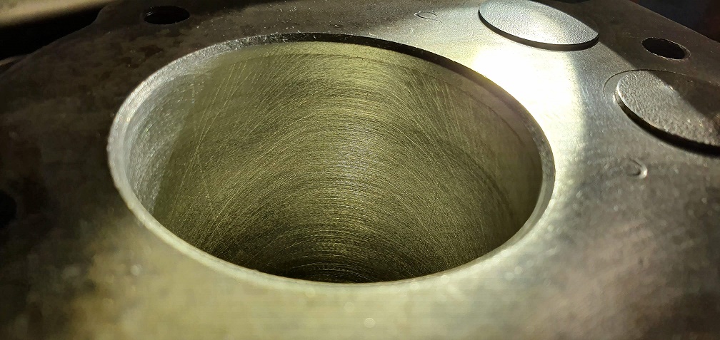
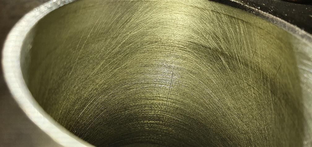
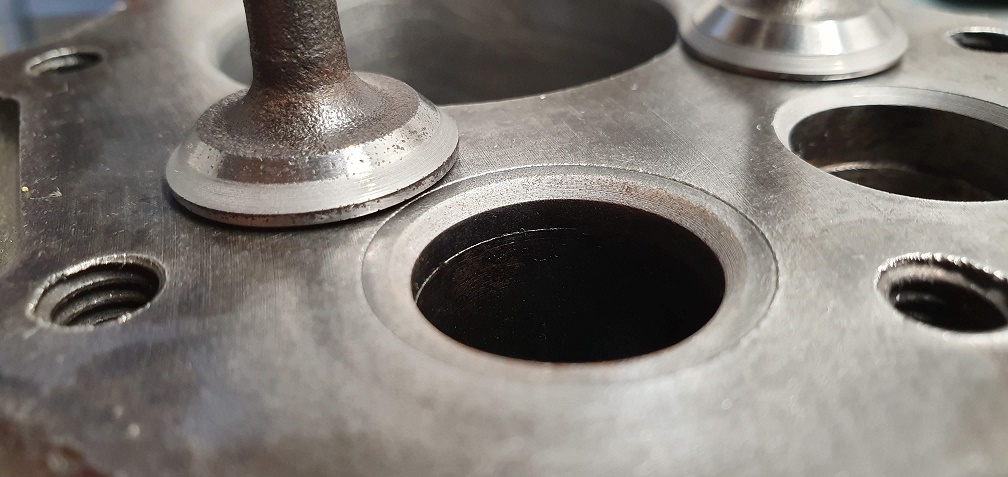
I'd appreciate some advice / opinions from anyone readying on my first attempt at honing the cylinder block please. I used a draper 3 legged small sized honing tool with my drill rotating very slowly and moving up and down to get approx one up and one down stroke for each revolution of the drill. I read this should help to obtain the desired 45 degree angle.I used the slightly more than the minimum pressure on the adjusting knurled disc and the stones are 220 grit - using GT85 as lubricant. I can still see previous 'staining' marks from before on the cylinder walls, and I'm not entirely sure If I've done enough, as I can see lots of upside down 'U' shapes but not the cross hatch pattern I was expecting. It has taken away some of the glazing, but perhaps more pressure on the stone legs and a bit more working is required? Pictures to follow shortly...
And under a different light
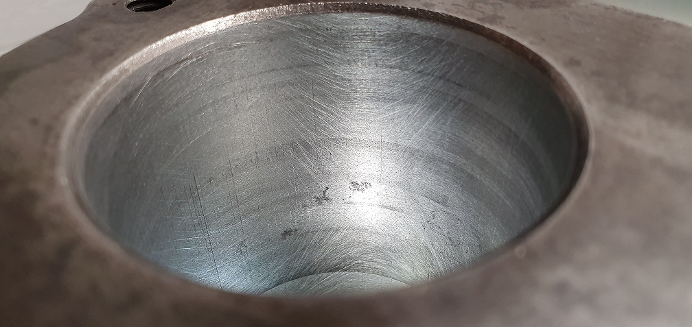
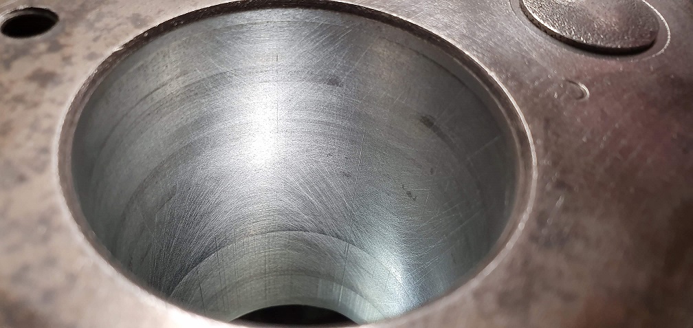
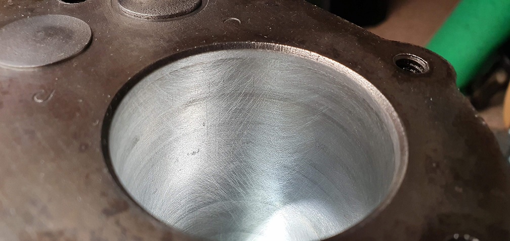
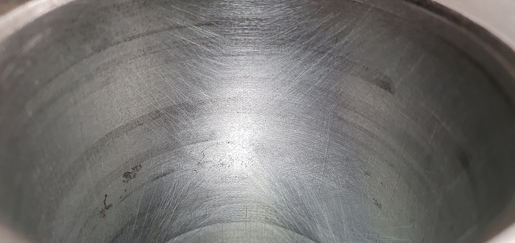
And under a different light
I started to answer your post
I started to answer your post before you added the second one with the images but got called away - however.
Normal rotational speed is 350 -550 rpm with say 36 complete strokes (down and up) per minute . The final ten being "rapid" . That should give a satisfactory cross hatch.
As you appear to have done the "heavy cutting" you might like to just try a quick burst of 10/20 rapid strokes and see what result you get.
Normal advice is to limit the travel of the stones to no more than 3/4 " above / below the bore.
Not sure about GT85 as a lubricant, I use Duck Oil or Kerosene
Just bear in mind that you are glaze busting and surface preparing the bore for standard rings - not re-sizing.

Re the subject of the dowel
Re the subject of dowel pins that locate the sump pan I noticed yesterday that the dowels on the engine that I have here has roll pins for dowels, exactly the same as the set shown earlier in this thread - but no cracks.
Thanks Hillsider, that's
Thanks Hillsider, that's interesting - I wonder if someone replaced the dowels in your engine at some point in it's history with whatever was available at the time, which happened to be roll pins? Or maybe they are original and were used in the original assembly for a period perhaps.
Angus - thank you for the explanation regarding honing. I might do a few more final passes just to see if it looks any different, but I think maybe the stones are a bit on the short side for the depth of the cylinder, as they are only 30mm long. The larger tools I have seen were recommended for cylinders in excess of over 50mm diameter, so I avoided those. Anyway, I'm sure it's going to be good enough for the new rings.
Finished lapping the valves as best as possible. The grey bands on both inlet and exhaust are wider than they really should be, and right up against the margin instead of midway down the valve face, but without sending the block off for valve seat and guide work/replacements and new valves, I think this is as good as it's going to get, and will hopefully run ok
Inlet valve
Inlet valve seat before and after
Exhaust
My first experience with the lapping stick and the sucker not staying stuck to the valve face was mildly amusing/frustrating!!
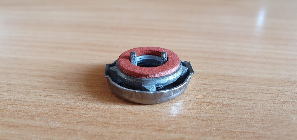
I managed to get hold of a new crankcase breather body and washer, as my original had one of its locating legs broken, so I now have a full breather setup ready to refit when the time comes
And assembled
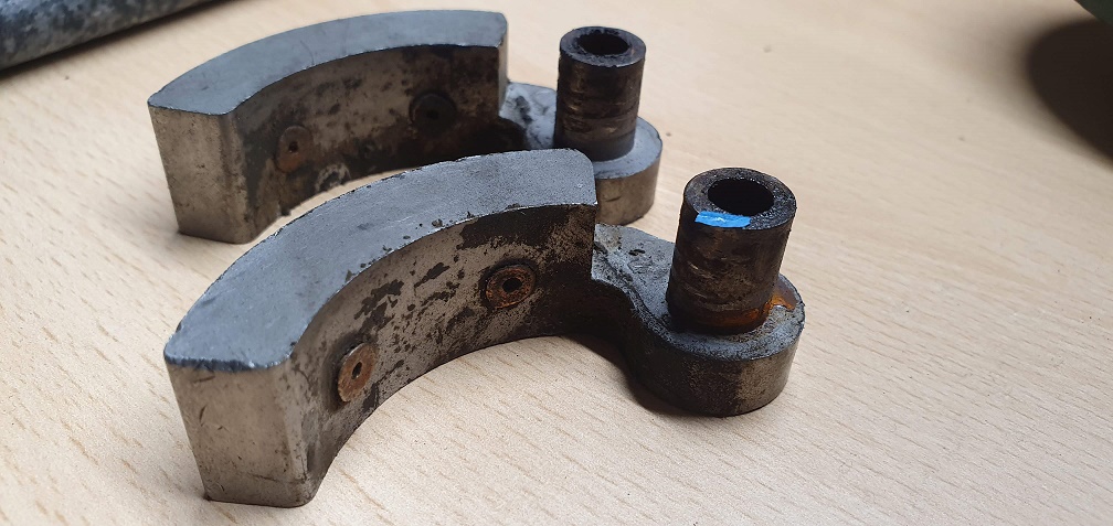
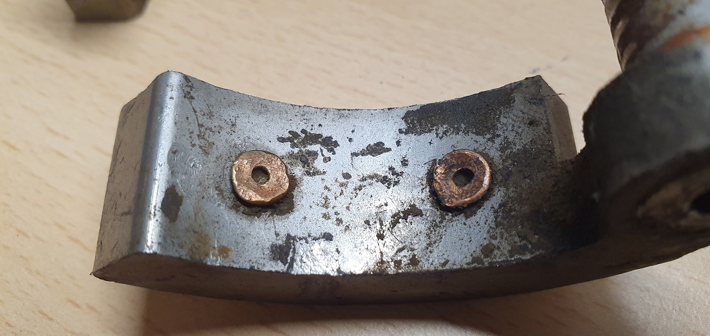
Also I managed to source some new clutch shoe liners and rivets, as my liners were non-existent
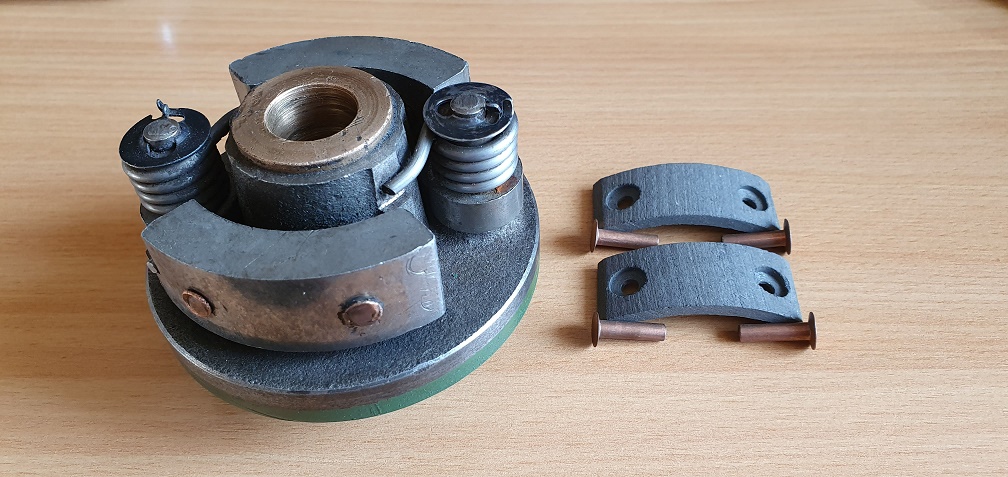
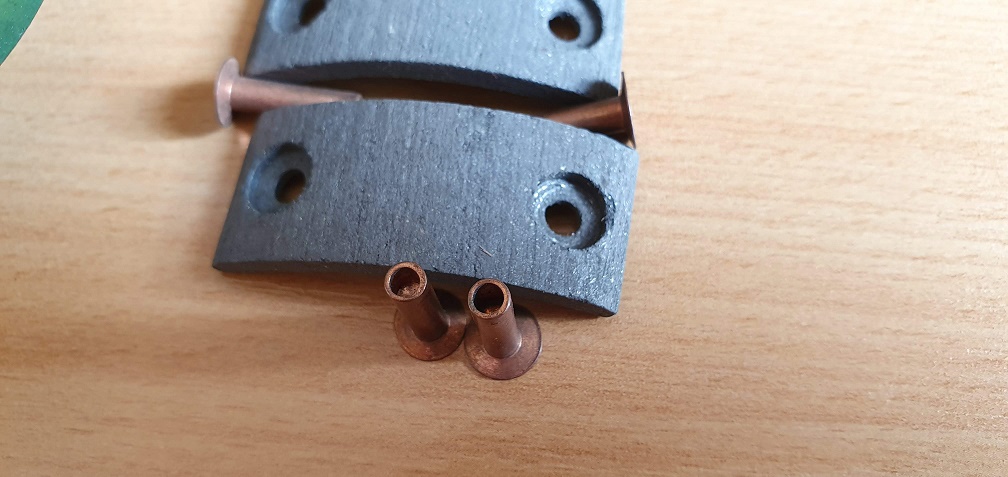
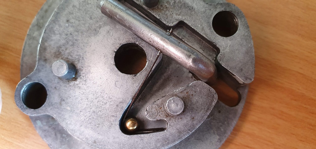
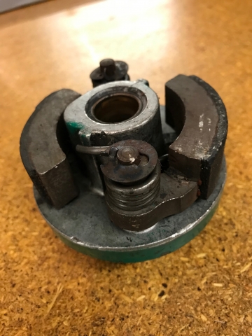
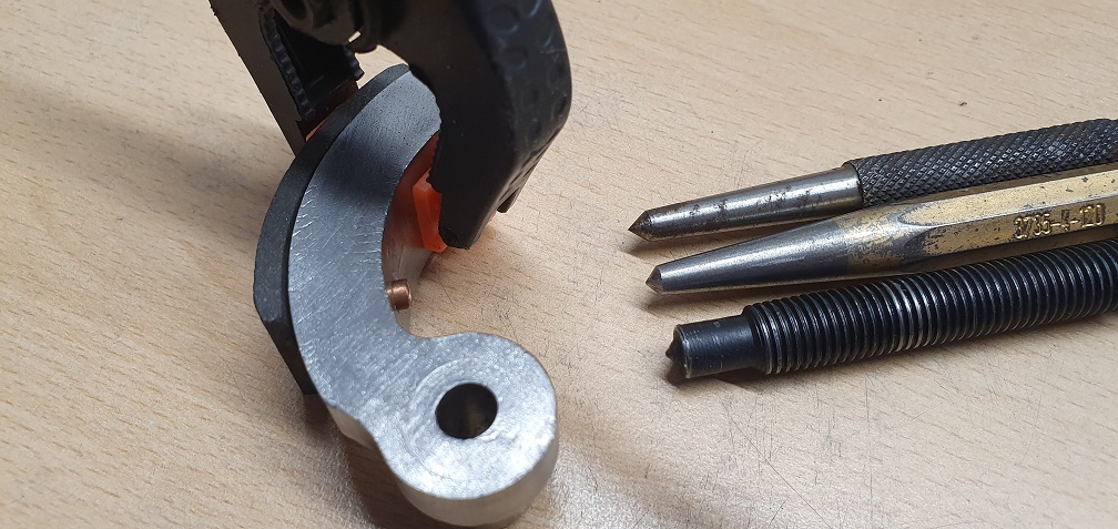
Can anyone explain how the new liners are riveted on? Is there a special tool required for spreading out the back side of the rivet onto the back of the brake shoe? The last 5/6mm of the rivets are hollow on the back end, but I can't find any information on how to fit these - although I am aware that they can also be bonded to the shoes instead. Any advice appreciated. Also, should the pins shown here be sitting proud at the back of the clutch like they are?
Remove the shoes from the
Remove the shoes from the backplate and clean off any trace of old lining. . Find a flat ended punch fractionally smaller than the rivet head and a fairly broad shallow point centre punch. Mount the flat punch upside down in the vice, thread the rivet through the lining and the shoe and balance it’s head on the flat end of the punch . Place the centre punch on the open end of the rivet and tap it with a hammer just enough to expand / collapse it enough to tighten the lining against the shoe.
Or, forget the rivets and glue the linings to the shoes with one of the current wonder adhesives.
I second wristpins method of
I second wristpins method of riveting the linings to the shoes, I think I would persevere with the rivets as the glues used by brake relining companies tend to be heat cured under pressure.
If the rivets are copper you may find them easier to close if you anneal them first by heating them to cherry red them quenching them in water.
When you refit the clutch shoes don't overdo the lubrication, any excess will only find it's way onto your new linings.
Thank you both very much for
Thank you both very much for the advice, appreciated. I'll see if I can get hold of some suitable punches, as I don't have any, and give it a try.
I think I got lucky with my
I think I got lucky with my twizzle stick, it has only let go a few times although a magnetic one I made did work well as long as the valve was magnetic.
Re punches, good idea to buy a good selection as a roll set, the more the better, always handy with lots of sizes and not expensive. I wonder if a riveter would work?, likely not as there is too much depth?
Do you mind sharing where you got the replacement linings?
Hi Chris, sure thing - I
Hi Chris, sure thing - I ordered my replacement lining and rivet set from Jon at the Mower Centre Hailsham https://www.themowercentrehailsham.com/ at a very reasonable price, and a lot cheaper than the very few alternatives around!
I'll see what I can find online in term of a punch set, or browse the local market stall, as there is a great stall locally which has a large selection of new and used tools of all sorts! Could probably spend an entire afternoon browsing :)
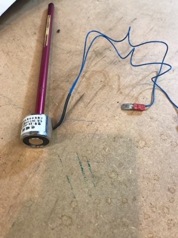
P.S The twizzle stick magnet idea could work If I need to do it again in future - perhaps even gluing a small magnet to both valve and suction cup. I did wonder about trying some sticky back velcro on both surfaces as well just to maintain the contact. The Draper stick (plastic) I ordered arrived bowed like a banana, so I had to remove the suction cup and put it on the end of a straight piece of wood instead!
I've found a couple of
I've found a couple of pictures in a thread online where someone is doing something similar but on brake shoes. Looks very much like what has been suggested above
https://www.triple-mregister.org/forums/topic.asp?ARCHIVE=true&TOPIC_ID=9718
I think I got lucky with my
I think I got lucky with my twizzle stick, it has only let go a few times although a magnetic one I made did work well as long as the valve was magnetic.
Re punches, good idea to buy a good selection as a roll set, the more the better, always handy with lots of sizes and not expensive. I wonder if a riveter would
work?, likely not as there is too much depth?
These are the dog's doodahs of twizzle sticks with a built in vacuum pump but a trifle pricey for a one off job. However they do save a lot of frustration !
https://www.buyamower.co.uk/product/briggs-stratton-valve-lapping-tool-19258.aspx
On the subject of shoe riveting I wonder if a small G clamp could be modified with a small nut on the anvil to push on the rivet head and the swivel pressure plate removed so that the ball end of the screw would press directly on the open end of the rivet. Perhaps with a drop of lubrication the ball end might give a steady controlled spread of the rivet?
If lapping was going to be
If lapping was going to be more than a one off job for me, I would definitely look at that B&S stick, what a great idea! Although my Draper one was exactly ten times less than that one costs - however only the suction cup was of any use!
That sounds like a cunning idea about the small G clamp, I'll dig one out and see if that might do the trick!
A couple of tools out there online but again pricey for a one off job
https://aircraft-tool.com/shop/detail.aspx?id=W403
https://www.lasaero.com/products/article/P03XTQZV9
and tricky trying to find either a single suitable punch or even a set which includes the correct size punch...
EDIT - Just found this which is the closest match so far to what is required as far as I can see
I have a small bearing puller
I have a small bearing puller which might actually do the trick. The threaded bar has a flat end with a point in the middle, which does fit inside the hollow end of the rivet
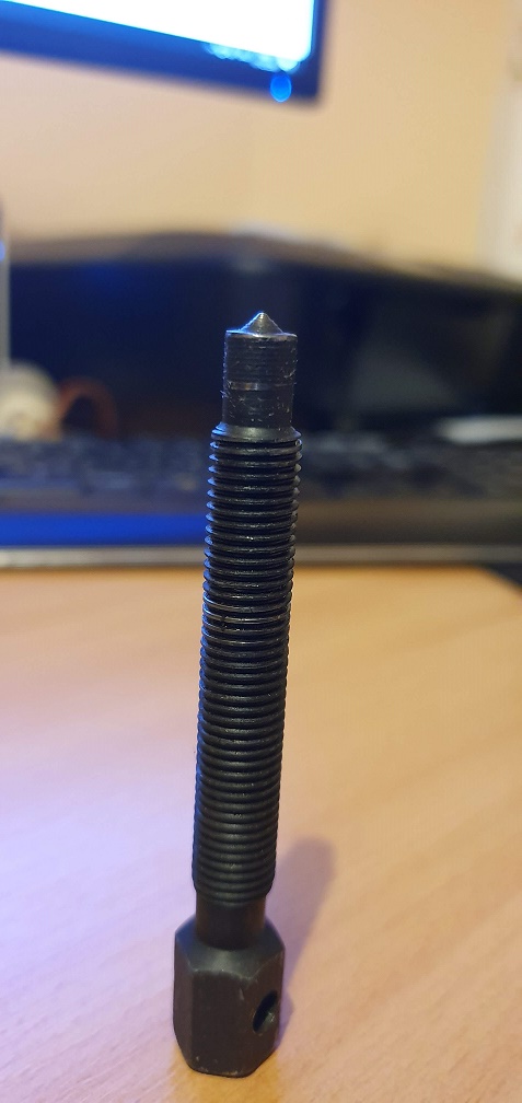
The last thing I want to do is make a pigs ear of it by using the wrong tool for the job, but do you think tapping this down onto the rivet would have the desired result, or does it not really have the right sort of profile?
Thanks for the info re the
Thanks for the info re the linings - good to know!
That Briggs twizzle stick looks the business, serious trouble free twizzling wth that.
The solenoid one pictured works really well, I just came across a non magnetic valve which put a bit of a downer on it...
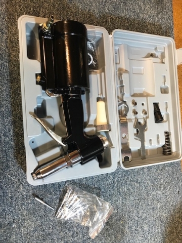
Re the rivet, think the G clamp idea could work well, if I ever get round to doing the same I might try the rivet gun, these are the biggest rivets I have at 20mm x 4mm so would probably need bigger, being steel this air riveter makes short work, very hard with a hand riveter..
On the punches, I've acquired a few over the years but the one in that link seems quite a lot for what it is, ebay or amazon etc do decent selection sets for a lot cheaper, this is one set I have - https://www.ebay.co.uk/itm/Blue-Spot-Tools-Heavy-Duty-Punch-Drift-Metal-Chisel-14pc-Set-Tool-Roll-22451/162198095309?epid=648108196&hash=item25c3c285cd:g:GYwAAOSwGtRX1C06
Thanks Chris, that solenoid
Thanks Chris, that solenoid one looks interesting :) and thanks for the example tool roll. I'll keep an eye out for a kit which ideally has the size tool i'm after currently, as it would make more sense than spending more on just a single tool which will have a, more than likely, single time use.
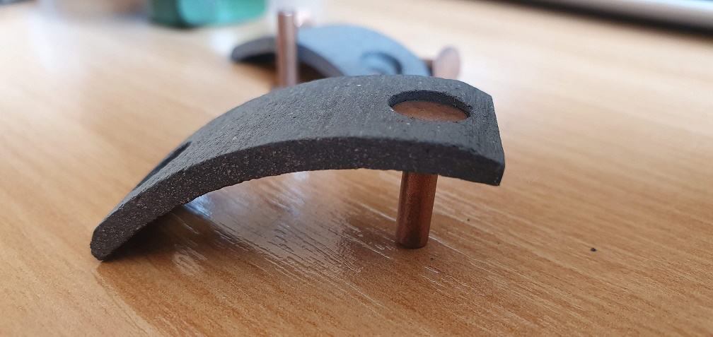
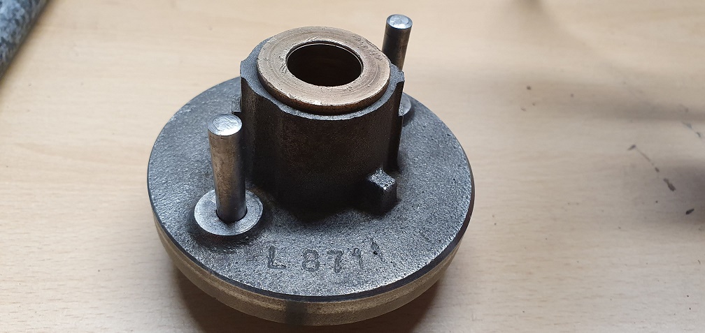
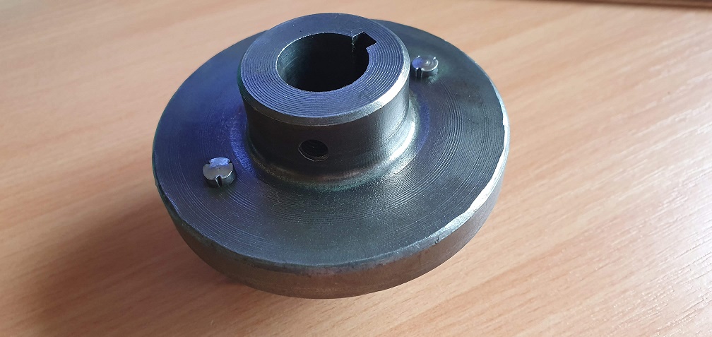
Can anyone confirm if these legs/pins/shafts should be flush at the back, or protruding like they are? Didn't seem to be much 'meat' for the little circlip type washers to grip onto to (which sit above/retain the springs on the other side), so wondered if these should sit flush?
Shoes will need a good clean up as were quite rusty on the shafts
I knew I had one in the
I knew I had one in the spares, but a later ali punch so not a useful comparison, but these liners are definitely glued.
Hopefully a better comparison with the right thing will be replied.
Loosing track of the
Loosing track of the questions! Clutch pivot pins - if they are tight I would leave them as is, those clips seem to grip OK
Rivet peening. I'd aim to expand the rivet more than crushing it.

Chris - thanks for posting
Chris - thanks for posting those clutch pictures, the later ones with the cam lobe-esque centre do seem a bit more common, although I found one clutch the same as my one with the linings bonded and no countersunk holes for rivets - perhaps some after market linings were fitted.
Angus - thank you for those punch pictures, it's helpful to see the sort of thing I'm looking to get hold of. Still searching at the moment - checked with the local small ish garage but they couldn't help and suggested an engineering firm locally that may be able to assist if I cant find the right tool. I've also had a quote of around £20 all in inc postage for a company to rivet them on if I send them off, so I have that as a backup option, but would prefer to do them myself for the learning experience if nothing else.
Certainly no need to send
Certainly no need to send them away - time to improvise! Do you have access to a bench grinder? If so just get a bit of rod and grind a shallow point on it. Its only got to do the four soft copper rivets, so no need to worry about hardening etc. Failing that just tap them carefully with the ball end of a ball pein hammer.
Your's are almost certainly genuine Qualcast shoes and linings which were superceded by the bonded pattern back in the 80s.
For another reason fellow OLC member Hillsider (Ray) and I have been engaged in a bit of research on Qualcast centrifugal clutches - not relevant to your issues so I wont muddy the waters for now but may open a thread for discussion at a later date.
Hi. Have only recently joined
Hi. Have only recently joined but already found this thread (& others!) really interesting. Well done in persevering with this rebuild your doing a great job! Not wanting to jump the gun but regarding Atco green, if you can't obtain the genuine paint at a reasonable price I've heard that RAL 6010 grass green is extremely close to the original shade.
Hi Jonson - welcome to the
Hi Jonson - welcome to the club :)
I'm glad you've found the thread interesting so far, if it helps other people to learn about these mowers or even provides an interesting read then that's great. Thanks for the kind words, i'm learning a lot form this project and determined to achieve a good result at the end. I couldn't have got this far without the wealth of knowledge that other club members have and have kindly shared.
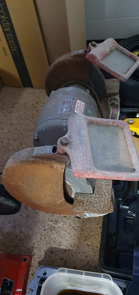
Wristpin - thanks for the inspiration to get creative! I did inherit an old bench grinder which could do with a restoration at some point, but it does at least work - i've just never used it...
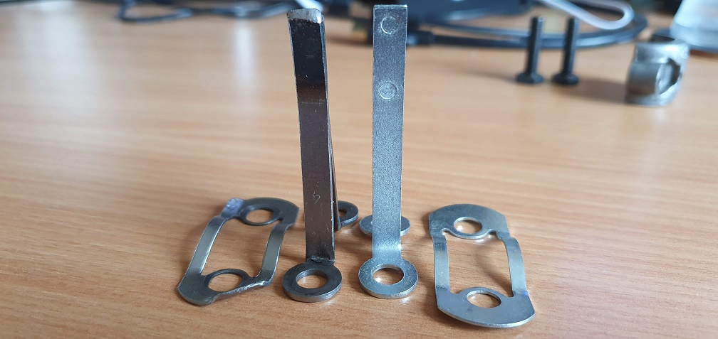
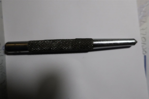
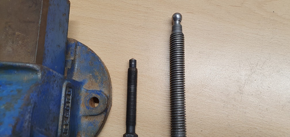
I borrowed a couple of centre punches from a friend but they weren't quite shallow enough a point, so i decided to modify the threaded rod from my little bearing puller
After modification using the bench grinder - alongside the other tool which I would use - the threaded rod from a 4" clamp - minus the swivel head
After trial fitting the
After trial fitting the rivets, they fitted fine into the linings until the linings were applied to the shoes. The heads of the rivets wouldn't quite sink down into the countersunk parts of the linings easily, well, the first one on each shoe would, but the second one then wouldn't - so I popped each of the rivets gently into the end of my drill and ran some emery paper over the edge of the heads, to just shave a fraction off the diameter - this allowed the heads to sink down into the linings properly, and would hopefully avoid cracking the linings when setting the rivets etc
A before and after
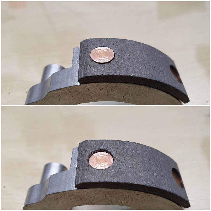
So holding a 7mm piece of rod in the vice to support the rivet head, and with the help of my other half to hold things steady, I began setting the rivets. Starting off with my modified shall point item to start spreading the hollow underside part of the rivet with some gentle taps with the hammer, then finishing with the ball shaped part of the clamp and again some gentle taps with the hammer all round the edges to flatten them down
First rivet set - pleased with myself!
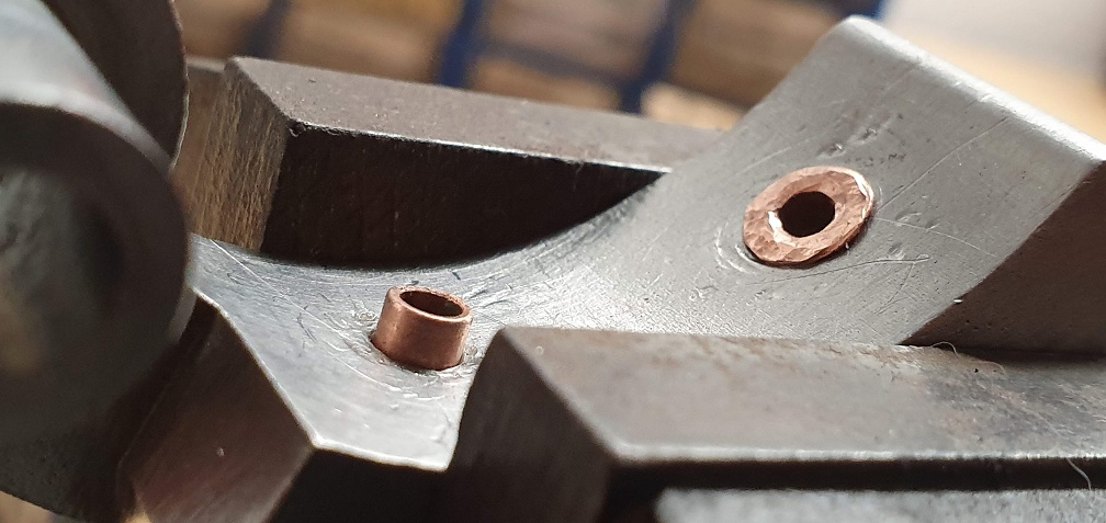
Both rivets set on the first shoe, so moved onto the second shoe - however on the final rivet, the end of the rivet split before i started using the ball shaped tool :(
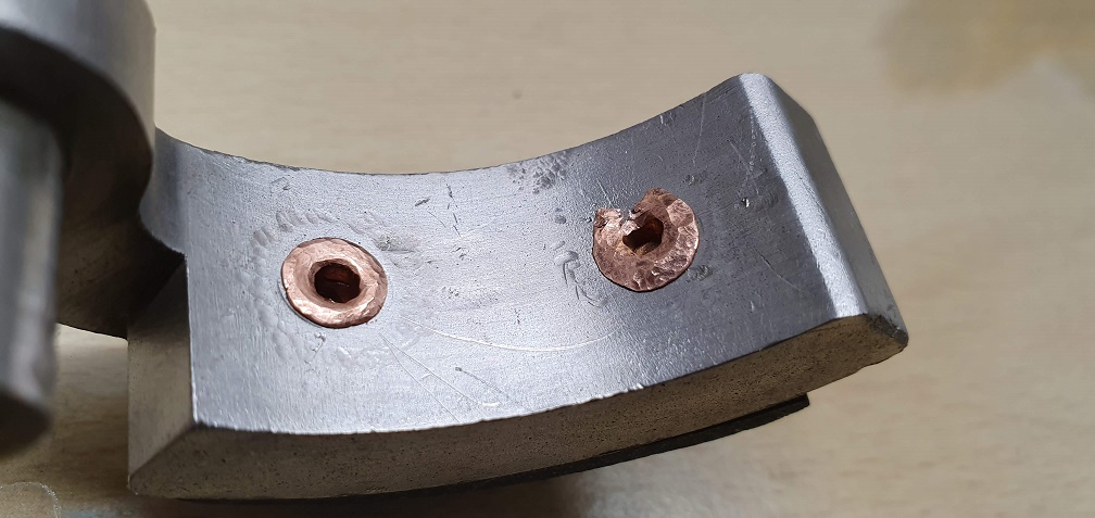
Absolutely gutted. I carried on and finished it, but I'm not sure whether or not it will be ok like this? I think it probably will, as over 3/4 of the rolled section is perfectly fine, so I can't see it being able to go anywhere. However, knowing it's not 100% right is really bugging me and i'm kicking myself now. Maybe I was getting too confident with the technique, or perhaps that rivet had a slight weakness or something. Stupidly I didn't measure all the dimentions of the rivets, but I know the head diameter and the hollow part diameter, so I'll have to try and source a replacement so I can re-do this one.
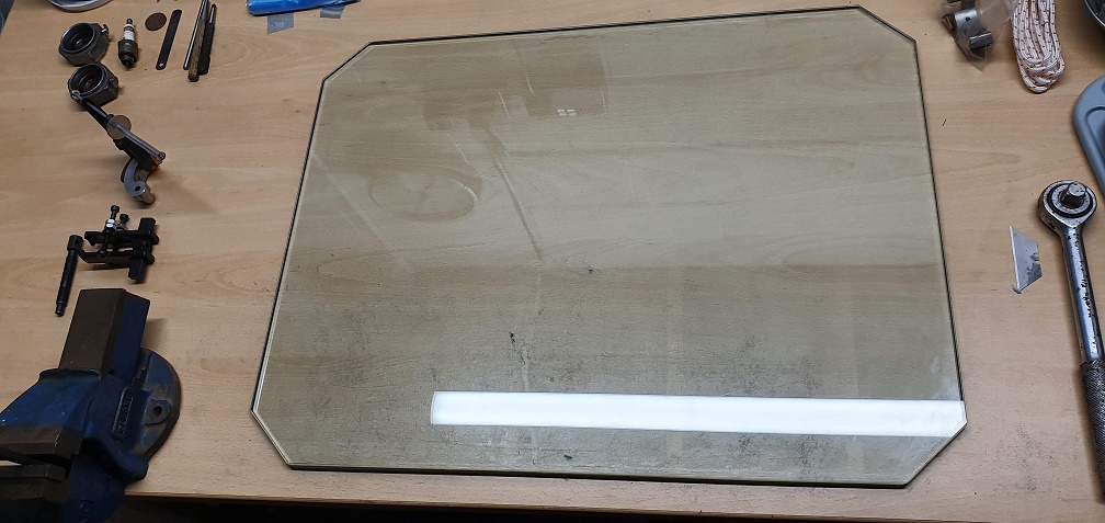
Oh well, still happy with the way the other 3 turned out! Plus, I managed to get hold of a pane of glass locally which is 9.5mm thick and plenty big enough to act as a nice flat surface for cleaning up the gasket faces of the engine
A good effort there and also
A good effort there and also good that you spotted the head of the rivet not sitting in it's counter bore correctly, by not rectifying that you could have caused the lining to split as the rivet was closed.
It has to be your personal choice re replacing the split rivet or leaving well alone but given the job that it is doing I think it will be fine, if it was a brake lining on a vehicle then I would think differently.
Thanks hillsider, I
Thanks hillsider, I completely agree - I expect it would be fine for it's intended use, unlike if it were on a vehicle brake lining. However me being me, it's already niggling away when trying to convince myself to just leave it be, so I'm going to (have to) re-do it! Jon at the mower centre is going to sort me out with another copper rivet, and I'll measure all dimensions of it when I get it, for reference, before removing and replacing the split one. Then I can rebuild the clutch and that will be another job ticked off. Does anyone know whether the back of the clutch shoe backing plate (where the pins poke through a few mm) would have been painted originally? I couldn't see any traces of original Atco green on it, just the overpaint layer, so would it have just been bare metal and coated with something to prevent rust? Just so I know whether to add it to the pile of parts requiring Atco green or not
Never seen one that was not
Never seen one that was not painted, but then I’d never seen a cracked crank either !
Thanks Angus, painted it is
Thanks Angus, painted it is then. I'll hold off on rebuilding the clutch with the shoes etc in that case until after painting.
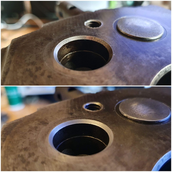
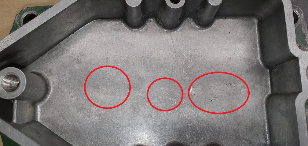
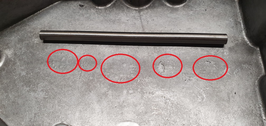
Another oddity which I've noticed - I'm not sure if it has been there the whole time, and I've only just noticed, or if this is a recent issue. My sump seems to have developed what I can only describe as slight 'Blistering' on the inside on the bottom of the sump in the middle. I've taken some pictures to show what I mean, but I'm wondering if this is a recent reaction to something...
There has always been a 'scuff' mark in the sump which I put down to the dipstick hitting it constantly, or the oil flicker hitting the sump (which turned out to not be the case), but perhaps this was part of the same problem
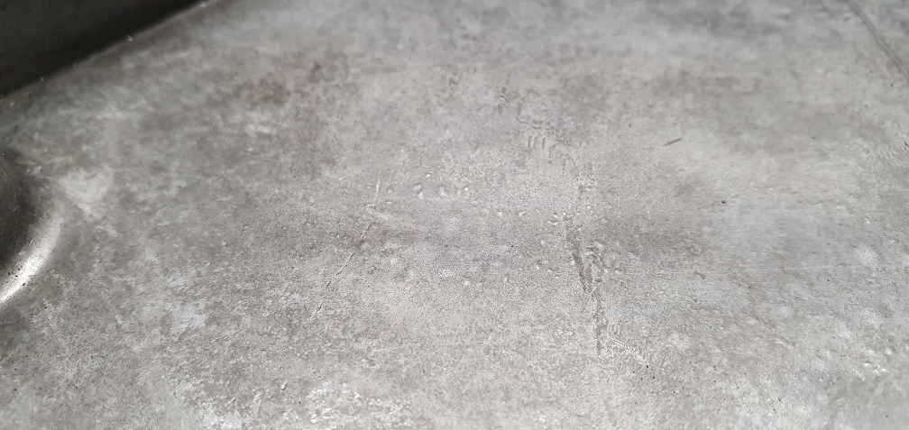
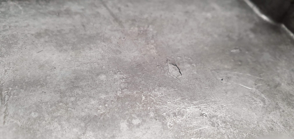
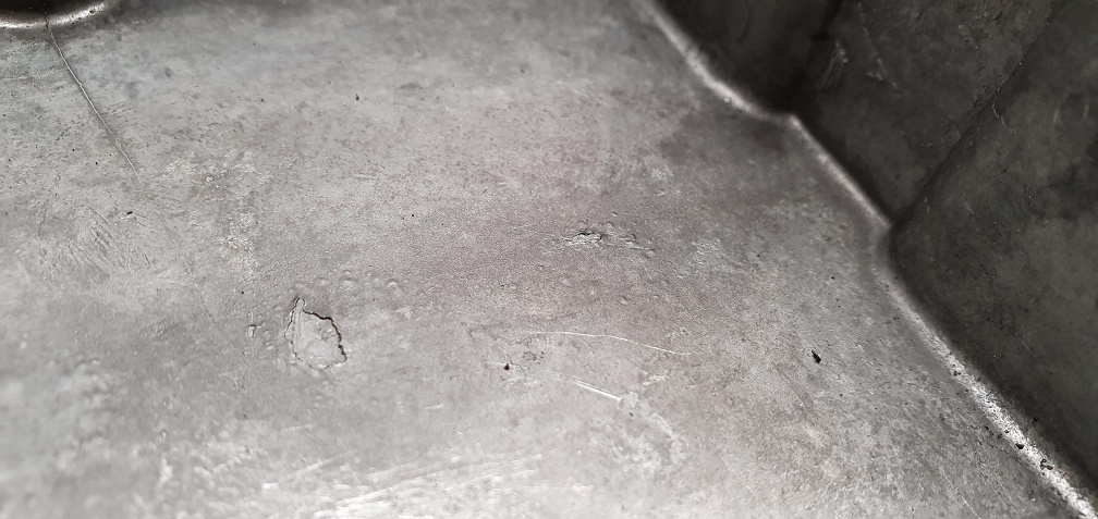
Potential brainwave - the
Potential brainwave - the small length of Silver Steel rod that I bought to make the replacement dowels for the sump was lying in the middle of the empty sump for a couple of weeks or so - could the aluminium sump have reacted with the silver steel? I know stainless steel can react with aluminium, but not sure about this silver steel? The steel rod does have a dark line running down the length of it, on the resting surface which was in contact with the sump - possible sign of a reaction?
That is possible, especially
That is possible, especially if conditions are damp.
I wouldn’t worry about it.
I wouldn’t worry about it. Guessing that it may have been caused by a chemical reaction to previous dirty oil; maybe contaminated with a bit of water and the acidic products of combustion.
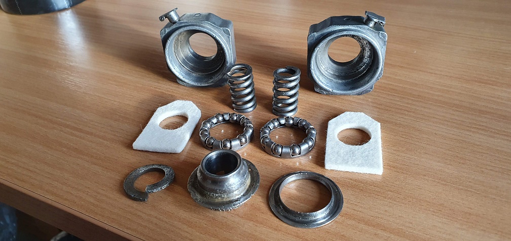
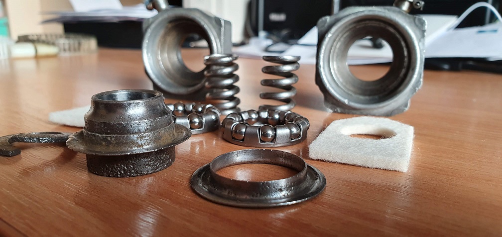
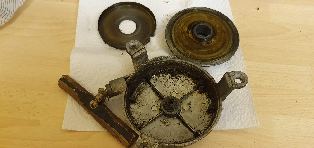
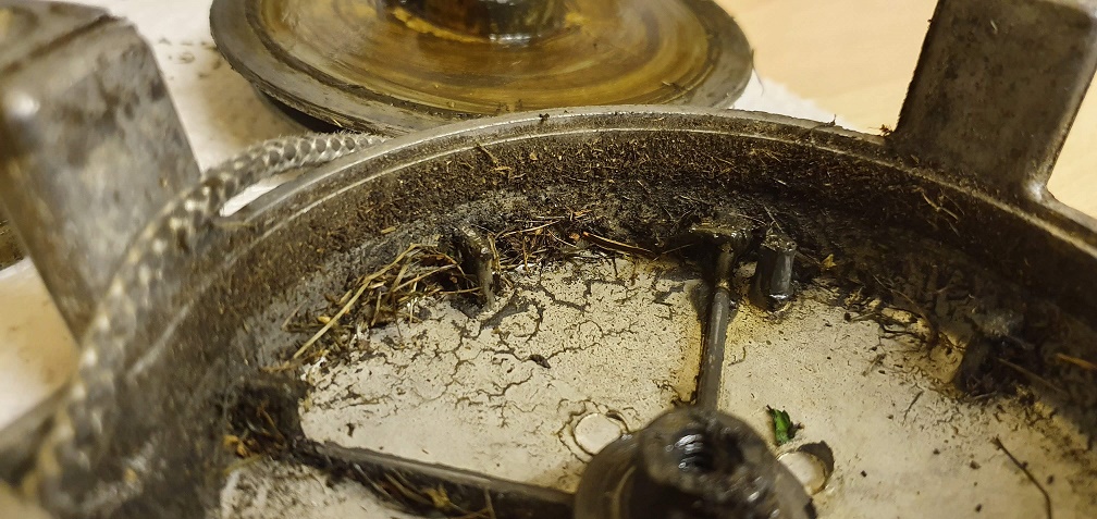
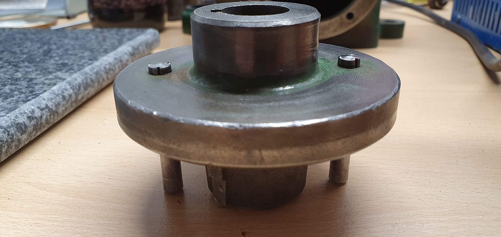
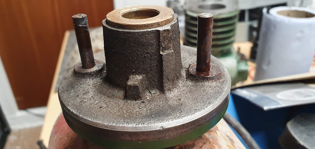
The side plates for the
The side plates for the cylinder are pretty grubby so will need a good clean up, but nuts, bottom blade adjusters etc all seem present and accounted for
Ordered some new felt pads for the bearing blocks / carriers
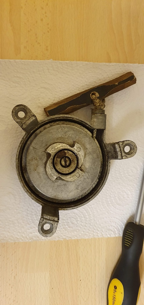
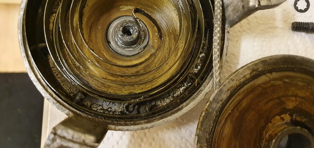
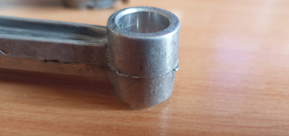
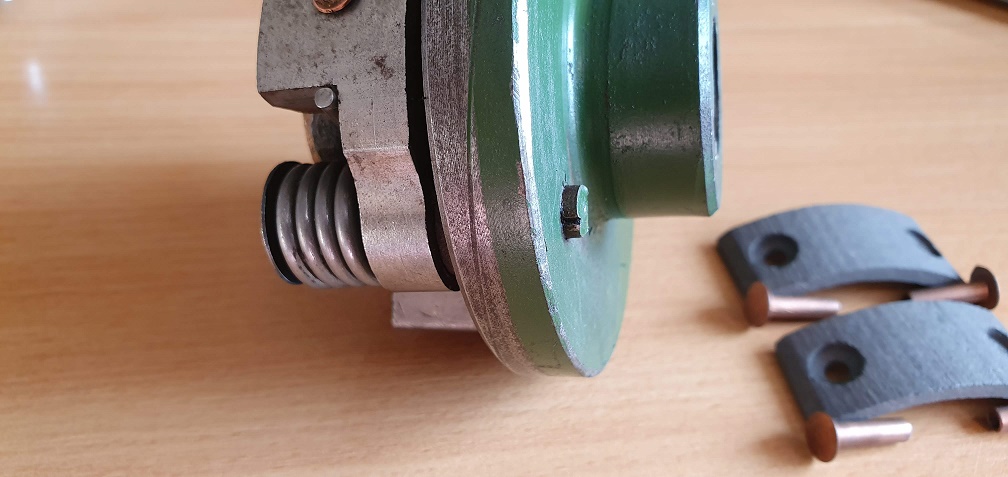
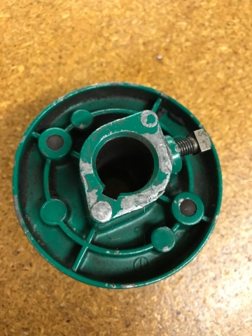
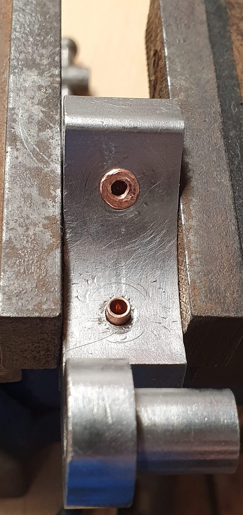
I've noticed there is quite a lot of vertical slop in the clutch drum shaft - as indicated by the arrows in this picture - I haven't measured the amount, but should there be a degree of movement here to accommodate the centrifugal clutch shoes when they start expending and contacting the drum?
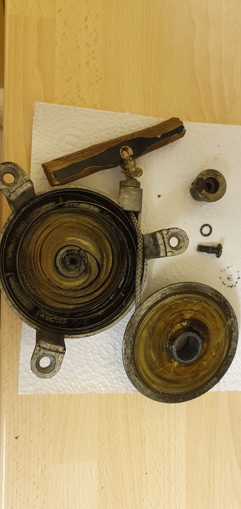
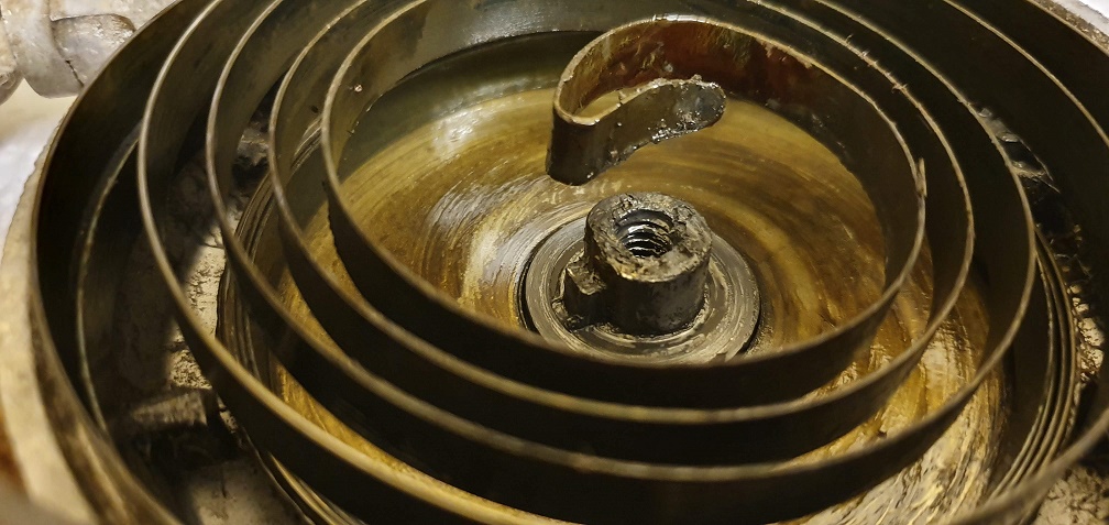
Finally, to remove this nut on the top drive sprocket, can you suggest any way of holding the clutch drum still in order to free the nut?